Service Guide
Page 7
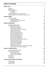
... Tour 1 Features 1 Block Diagram 4 System Components 5 Front Panel 5 Rear Panel 6 Hardware Specifications and Configurations 7 Power Management Function(ACPI support function) 10 System Utilities 11 CMOS Setup Utility 11 Entering CMOS setup 12 Navigating Through the Setup Utility 12 Setup Utility Menus 13 System Disassembly 26 Disassembly Requirements 26 Pre-disassembly Procedure 27...
... Tour 1 Features 1 Block Diagram 4 System Components 5 Front Panel 5 Rear Panel 6 Hardware Specifications and Configurations 7 Power Management Function(ACPI support function) 10 System Utilities 11 CMOS Setup Utility 11 Entering CMOS setup 12 Navigating Through the Setup Utility 12 Setup Utility Menus 13 System Disassembly 26 Disassembly Requirements 26 Pre-disassembly Procedure 27...

Service Guide
Page 13
... the removable HDD. 2 USB 2.0 ports 9 MS/MS PRO slot 3 Master optical drive crab 10 SD/MMC(Secure Digital/MultiMedia Card)slot 4 Slave optical drive crab 11 Master optical drive button Press to open master optical drive crab and access the master optical drive. 5 XD(XD-Picture) slot 12 Slave optical drive... SD slot 13 Microphone-in jack 7 CF I/II (CompactFlash Type I/II) slot 14 Headphone/Speaker-out/line-out jack Chapter 1 5 Front Panel 1 2 14 13 3 4 12 11 5 6 10 7 8 9 No.
... the removable HDD. 2 USB 2.0 ports 9 MS/MS PRO slot 3 Master optical drive crab 10 SD/MMC(Secure Digital/MultiMedia Card)slot 4 Slave optical drive crab 11 Master optical drive button Press to open master optical drive crab and access the master optical drive. 5 XD(XD-Picture) slot 12 Slave optical drive... SD slot 13 Microphone-in jack 7 CF I/II (CompactFlash Type I/II) slot 14 Headphone/Speaker-out/line-out jack Chapter 1 5 Front Panel 1 2 14 13 3 4 12 11 5 6 10 7 8 9 No.

Service Guide
Page 14
Component 1 Power connector 2 PS2 keyboard port 3 USB 2.0 ports 4 Line-out jack 5 Microphone/speaker-out/line-in jack 6 Expansion slot(graphics card and Mode card etc.) 7 Line-in jack 8 RJ45 LAN connector 9 System Fan 10 PS2 mouse port Line-out jack 11 USB 2.0 ports 12 Power switch 6 Chapter 1 Rear Panel 1 12 11 2 10 9 8 3 4 7 5 6 No.
Component 1 Power connector 2 PS2 keyboard port 3 USB 2.0 ports 4 Line-out jack 5 Microphone/speaker-out/line-in jack 6 Expansion slot(graphics card and Mode card etc.) 7 Line-in jack 8 RJ45 LAN connector 9 System Fan 10 PS2 mouse port Line-out jack 11 USB 2.0 ports 12 Power switch 6 Chapter 1 Rear Panel 1 12 11 2 10 9 8 3 4 7 5 6 No.
Service Guide
Page 19
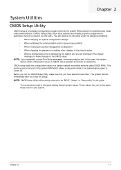
... that you have saved all open files. Ask a qualified technician for assistance. In this case, the system cannot retain configuration values in this utility. Chapter 2 11 Chapter 2 System Utilities CMOS Setup Utility CMOS setup is a hardware configuration program built into the system ROM, called CMOS RAM.
... that you have saved all open files. Ask a qualified technician for assistance. In this case, the system cannot retain configuration values in this utility. Chapter 2 11 Chapter 2 System Utilities CMOS Setup Utility CMOS setup is a hardware configuration program built into the system ROM, called CMOS RAM.
Service Guide
Page 68
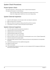
... , skip this section. If the system will power on a flat, stable surface. 6. Unplug the power cord from the power outlets. 3. Verify that all components are Acer-qualified and supported. 10. System Internal Inspection 1. Verify that all cable connectors inside the system are properly seated. 8. System Check Procedures Power System Check If... the system. 4. Remove the system covers.For instructions on , do the following: • Check if the power cable is not blocked. 3. Replace the system covers. 11. If the problem with System Internal Inspection.
... , skip this section. If the system will power on a flat, stable surface. 6. Unplug the power cord from the power outlets. 3. Verify that all components are Acer-qualified and supported. 10. System Internal Inspection 1. Verify that all cable connectors inside the system are properly seated. 8. System Check Procedures Power System Check If... the system. 4. Remove the system covers.For instructions on , do the following: • Check if the power cable is not blocked. 3. Replace the system covers. 11. If the problem with System Internal Inspection.

Service Guide
Page 75
No Label Description No Label Description 1 CPU Socket LGA1156 socket for Intel® 11 F_USB2 Lynnfield/Havendale/ Clarkdale processors Front panel USB header 2 CPU_FAN CPU cooling fan connector 12 F_USB1 Front panel USB header (Card Reader) 3 DIMM1~4 240-pin ...
No Label Description No Label Description 1 CPU Socket LGA1156 socket for Intel® 11 F_USB2 Lynnfield/Havendale/ Clarkdale processors Front panel USB header 2 CPU_FAN CPU cooling fan connector 12 F_USB1 Front panel USB header (Card Reader) 3 DIMM1~4 240-pin ...

Service Guide
Page 81
Pin Signal Name 5 Ground 6 +5V 7 Ground 8 PWRGD 9 +5VSB 10 +12V 11 +12V 12 +3.3V Pin Signal Name 17 Ground 18 Ground 19 Ground 20 -5V 21 +5V 22 +5V 23 +5V 24 Ground SYS_FAN1: System Cooling ... cases. Refer to the table below forinformation: Pin Signal Name Function 1 VCC 5V 3 HDD_LEDN Hard disk LED 5 GND Ground 7 HWRST_L Reset 9 F_PANEL_DET FRONT PANEL DETECT 11 NC Reserved 13 NC Reserved Pin Signal Name Function 2 GLED0 MSG LED 4 GLED1 MSG LED 6 PWRSW Power Switch 8 GND GROUND 10 KEY No pin 12...
Pin Signal Name 5 Ground 6 +5V 7 Ground 8 PWRGD 9 +5VSB 10 +12V 11 +12V 12 +3.3V Pin Signal Name 17 Ground 18 Ground 19 Ground 20 -5V 21 +5V 22 +5V 23 +5V 24 Ground SYS_FAN1: System Cooling ... cases. Refer to the table below forinformation: Pin Signal Name Function 1 VCC 5V 3 HDD_LEDN Hard disk LED 5 GND Ground 7 HWRST_L Reset 9 F_PANEL_DET FRONT PANEL DETECT 11 NC Reserved 13 NC Reserved Pin Signal Name Function 2 GLED0 MSG LED 4 GLED1 MSG LED 6 PWRSW Power Switch 8 GND GROUND 10 KEY No pin 12...

Service Guide
Page 84
ITEM 1 2 3 4 5 6 7 8 9 10 11 12 13 NAME 1-RIGHT-SIDE-X1 2-TOP-COVER CHASSIS-HANDLE 2-TOP-COVER07 1-TOP-PLATE SCREW_M632-6 G5-ASSY-FRONT-IO-BDNEW1_ASM(TOP IO) 1-ODD-BKT-X4 1-FBB-PLATE-0611 16IN5-WITH-1394-X1_ASM(MCR) HT-361-HDD-CARRIER 2-FRONT-COVER GJ-HDD-BKT-NEW Q'TY 1 1 1 1 1 20 1 ITEM 14 15 16 17 18 19 20 NAME 1-HDD-BKT-X2 THUMB-SCREW-2 HDD-RUBBER CUS-LV2122K 1-LETF-SIDE-X1 35FNF_AOO 2-PCI-SHIELD 1 21 CABLE-CLIP 1 22 PCI-DOOR-01 1 23 ACER_JOPLIN_RUBBER-BACK-FOOT 2 24 1-MB-BKT-X4 1 25 ATX-POWER-AA 1 26 1-BACK-X4 Q'TY 1 1 2 2 1 4 1 2 1 4 1 1 1 Chapter 6 76
ITEM 1 2 3 4 5 6 7 8 9 10 11 12 13 NAME 1-RIGHT-SIDE-X1 2-TOP-COVER CHASSIS-HANDLE 2-TOP-COVER07 1-TOP-PLATE SCREW_M632-6 G5-ASSY-FRONT-IO-BDNEW1_ASM(TOP IO) 1-ODD-BKT-X4 1-FBB-PLATE-0611 16IN5-WITH-1394-X1_ASM(MCR) HT-361-HDD-CARRIER 2-FRONT-COVER GJ-HDD-BKT-NEW Q'TY 1 1 1 1 1 20 1 ITEM 14 15 16 17 18 19 20 NAME 1-HDD-BKT-X2 THUMB-SCREW-2 HDD-RUBBER CUS-LV2122K 1-LETF-SIDE-X1 35FNF_AOO 2-PCI-SHIELD 1 21 CABLE-CLIP 1 22 PCI-DOOR-01 1 23 ACER_JOPLIN_RUBBER-BACK-FOOT 2 24 1-MB-BKT-X4 1 25 ATX-POWER-AA 1 26 1-BACK-X4 Q'TY 1 1 2 2 1 4 1 2 1 4 1 1 1 Chapter 6 76

Service Guide
Page 89
...) 100127V/220-240V PY.75008.005 PSU FSP FSP750-80APG 750W Active PFC (A01002) 100-240V PY.75008.003 WN7600R, WLAN PCI-Ex1 card 802.11 b/g/n 1T x NI.10200.008 N/A 2R, Ralink 1T x 2R, RT2790+RT2720 WN7601R, Ralink RT3090, 802.11b/g/n 1x1 WLAN PCI-E x1 card NI.10200.037 Mouse Keyboard...
...) 100127V/220-240V PY.75008.005 PSU FSP FSP750-80APG 750W Active PFC (A01002) 100-240V PY.75008.003 WN7600R, WLAN PCI-Ex1 card 802.11 b/g/n 1T x NI.10200.008 N/A 2R, Ralink 1T x 2R, RT2790+RT2720 WN7601R, Ralink RT3090, 802.11b/g/n 1x1 WLAN PCI-E x1 card NI.10200.037 Mouse Keyboard...

Service Guide
Page 98
...:Press "next" to OS desktop, open the Intel® Matrix Storage Console. Step 3:Boot to finish setup and start create RAID0. Chapter 7 90 Picture9 Step 11:It may takes half and hours to create RAID0.After create completely,it will ask to reboot to create a RAID volume. Step 4:Click on the...
...:Press "next" to OS desktop, open the Intel® Matrix Storage Console. Step 3:Boot to finish setup and start create RAID0. Chapter 7 90 Picture9 Step 11:It may takes half and hours to create RAID0.After create completely,it will ask to reboot to create a RAID volume. Step 4:Click on the...

Service Guide
Page 99
... on the by 'Create RAID Volume from Existing HDD Drive ' to finish create RAID1. 2-3:Create a"RAID Ready" System into" RAID 5" with one SATA HDD. Step 11:It may takes half and hours to create RAID1.After create completely,it will ask to reboot to create a RAID volume. Step 9:Specify Volume Size...
... on the by 'Create RAID Volume from Existing HDD Drive ' to finish create RAID1. 2-3:Create a"RAID Ready" System into" RAID 5" with one SATA HDD. Step 11:It may takes half and hours to create RAID1.After create completely,it will ask to reboot to create a RAID volume. Step 9:Specify Volume Size...

Service Guide
Page 101
... Hard Drives by 'Create RAID Volume from Existing HDD Drive '. Step 10:Press "next" to OS desktop, open the Intel® Matrix Storage Console. Step 11:It may takes half and hours to create RAID5.After create completely,it will ask to reboot to create a RAID volume. Step 3:Boot to finish...
... Hard Drives by 'Create RAID Volume from Existing HDD Drive '. Step 10:Press "next" to OS desktop, open the Intel® Matrix Storage Console. Step 11:It may takes half and hours to create RAID5.After create completely,it will ask to reboot to create a RAID volume. Step 3:Boot to finish...

Service Guide
Page 102
Step 11:It may takes half and hours to create RAID 10.After create completely,it will ask to reboot to create a RAID volume. Step 1:Install WIN7 ...
Step 11:It may takes half and hours to create RAID 10.After create completely,it will ask to reboot to create a RAID volume. Step 1:Install WIN7 ...

