
Aspire 7100/9400 and TravelMate 5100/5600 Service Guide
Page 5
These LOCALIZED FEATURES will not be covered in this printed Service Guide. Please note WHEN ORDERING FRU PARTS, that you should check the most up-to-date information available on card, modem, ... the functionality of this generic service guide. To better fit local market requirements and enhance product competitiveness, your regional web or channel. For ACER-AUTHORIZED SERVICE PROVIDERS, your regional Acer office to those given in the FRU list of a machine (e.g. Preface Before using this information and the product it will NOT be...
These LOCALIZED FEATURES will not be covered in this printed Service Guide. Please note WHEN ORDERING FRU PARTS, that you should check the most up-to-date information available on card, modem, ... the functionality of this generic service guide. To better fit local market requirements and enhance product competitiveness, your regional web or channel. For ACER-AUTHORIZED SERVICE PROVIDERS, your regional Acer office to those given in the FRU list of a machine (e.g. Preface Before using this information and the product it will NOT be...
Aspire 7100/9400 and TravelMate 5100/5600 Service Guide
Page 15
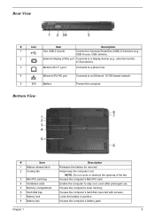
...'s battery pack. Enable the computer to an Ethernet 10/100-based network. 5 N/A Battery Powers the computer. Helps keep the computer cool. Note NOTNEot:eDo not cover or obstruct the opening of the fan. Bottom# ViIecown Item Description # # IItteemm 1 #BattIeterymrelease latch 2 Cooling fan 3 Mini PCI card bay 4 Ventilation slots 5 Memory compartment 6 Hard...
...'s battery pack. Enable the computer to an Ethernet 10/100-based network. 5 N/A Battery Powers the computer. Helps keep the computer cool. Note NOTNEot:eDo not cover or obstruct the opening of the fan. Bottom# ViIecown Item Description # # IItteemm 1 #BattIeterymrelease latch 2 Cooling fan 3 Mini PCI card bay 4 Ventilation slots 5 Memory compartment 6 Hard...

Aspire 7100/9400 and TravelMate 5100/5600 Service Guide
Page 16
... page 10 # Item "Launch keys" on page 10 Descrip"tiLonaunch keys" on page 10 "Launch keys" on page 10 #The Ifcroonnt paneItleinmdicators are visible wheDnetshcericpotmiopnuter cover is closed up when Num Lock is activated. Bluetooth Indicates the status of Bluetooth communication. Description Description Caps Lock activity Lights up when Caps Lock...
... page 10 # Item "Launch keys" on page 10 Descrip"tiLonaunch keys" on page 10 "Launch keys" on page 10 #The Ifcroonnt paneItleinmdicators are visible wheDnetshcericpotmiopnuter cover is closed up when Num Lock is activated. Bluetooth Indicates the status of Bluetooth communication. Description Description Caps Lock activity Lights up when Caps Lock...

Aspire 7100/9400 and TravelMate 5100/5600 Service Guide
Page 34
T View information about Acer ePower Management. 28 Chapter 1 T Select what actions will be taken when the cover is closed, and set passwords for accessing the system after Hibernation or Standby. You can also click "Advanced Settings" to: T Set alarms. T Re-load factory defaults.
T View information about Acer ePower Management. 28 Chapter 1 T Select what actions will be taken when the cover is closed, and set passwords for accessing the system after Hibernation or Standby. You can also click "Advanced Settings" to: T Set alarms. T Re-load factory defaults.

Aspire 7100/9400 and TravelMate 5100/5600 Service Guide
Page 55
...disassemble the notebook computer for the different components vary in size. During the disassembly process, group the screws with the corresponding components to scrape the cover. When you need the following tools: T Wrist grounding strap and conductive mat for preventing electrostatic discharge T Small Philips screw driver T Philips screwdriver... T Plastic flat head screw driver T Tweezers NOTE: The screws for maintenance and troubleshooting. To disassemble the computer, you remove the stripe cover, please be careful not to avoid mismatch when putting back the components.
...disassemble the notebook computer for the different components vary in size. During the disassembly process, group the screws with the corresponding components to scrape the cover. When you need the following tools: T Wrist grounding strap and conductive mat for preventing electrostatic discharge T Small Philips screw driver T Philips screwdriver... T Plastic flat head screw driver T Tweezers NOTE: The screws for maintenance and troubleshooting. To disassemble the computer, you remove the stripe cover, please be careful not to avoid mismatch when putting back the components.

Aspire 7100/9400 and TravelMate 5100/5600 Service Guide
Page 59
Disconnect the wireless antenna. 4. Remove the wireless LAN card. 5. Chapter 3 53 Remove the two screws securing the miniPCI cover. 2. Remove the two screws securing the RAM door and remove the RAM door. 6. Press the left and right latches to pop up the memory. Remove the miniPCI cover. 3. Removing the miniPCI/Memory/HDD Module/Keyboard Removing the miniPCI and Memory 1.
Disconnect the wireless antenna. 4. Remove the wireless LAN card. 5. Chapter 3 53 Remove the two screws securing the miniPCI cover. 2. Remove the two screws securing the RAM door and remove the RAM door. 6. Press the left and right latches to pop up the memory. Remove the miniPCI cover. 3. Removing the miniPCI/Memory/HDD Module/Keyboard Removing the miniPCI and Memory 1.

Aspire 7100/9400 and TravelMate 5100/5600 Service Guide
Page 60
Remove the HDD cover. 3. Release the four keyboard latches. 4. Remove the three screws that secure the HDD cover. 2. Pull the HDD outward a little bit and remove the HDD. Removing the keyboard 1. Remove the middle cover. 3. Disconnect the keyboard FFC from the mainboard. 54 Chapter 3 Removing the HDD 1. Open the notebook. 2. Pull the keyboard and trun it over. 5.
Remove the HDD cover. 3. Release the four keyboard latches. 4. Remove the three screws that secure the HDD cover. 2. Pull the HDD outward a little bit and remove the HDD. Removing the keyboard 1. Remove the middle cover. 3. Disconnect the keyboard FFC from the mainboard. 54 Chapter 3 Removing the HDD 1. Open the notebook. 2. Pull the keyboard and trun it over. 5.
Aspire 7100/9400 and TravelMate 5100/5600 Service Guide
Page 69
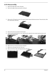
... release all latches as shown, and remove the inverter board. 6. Remove the four screws securing the LCD panel. 7. Remove the LCD bezel from the LCD cover. 8. Press the latch a little bit to remove the LCD bezel. 4. Remove the screw securing the inverter board. 5. Remove the LCD panel from the LCD module... left and right LCD hinge from the inverter board as shown. Pull the inverter board and turn it over, disconnect the cables from the LCD cover. 63 Chapter 3
... release all latches as shown, and remove the inverter board. 6. Remove the four screws securing the LCD panel. 7. Remove the LCD bezel from the LCD cover. 8. Press the latch a little bit to remove the LCD bezel. 4. Remove the screw securing the inverter board. 5. Remove the LCD panel from the LCD module... left and right LCD hinge from the inverter board as shown. Pull the inverter board and turn it over, disconnect the cables from the LCD cover. 63 Chapter 3

Aspire 7100/9400 and TravelMate 5100/5600 Service Guide
Page 70
Remove the four screws securing the left LCD bracket from the LCD panel. 13. Remove the antennas from the LCD panel. 15. Remove the right LCD bracket from the LCD cover. 11. Remove the left LCD bracket. 12. Remove the two screws securing the antenna. 10. Disconnect the LCD cable then remove it. Remove the four screws securing the right LCD bracket. 14. Chapter 3 64 Tear off the tape on the LCD cable. 16. 9.
Remove the four screws securing the left LCD bracket from the LCD panel. 13. Remove the antennas from the LCD panel. 15. Remove the right LCD bracket from the LCD cover. 11. Remove the left LCD bracket. 12. Remove the two screws securing the antenna. 10. Disconnect the LCD cable then remove it. Remove the four screws securing the right LCD bracket. 14. Chapter 3 64 Tear off the tape on the LCD cable. 16. 9.

Aspire 7100/9400 and TravelMate 5100/5600 Service Guide
Page 87
Connect AC adapter then check if the system resumes from standby mode LCD cover switch after opening the lid of the portable computer. Main board Press Fn+F5, LCD/CRT/Both display switching Keyboard Main board Main board Enter ...
Connect AC adapter then check if the system resumes from standby mode LCD cover switch after opening the lid of the portable computer. Main board Press Fn+F5, LCD/CRT/Both display switching Keyboard Main board Main board Enter ...
Aspire 7100/9400 and TravelMate 5100/5600 Service Guide
Page 96
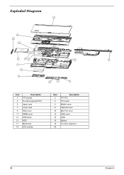
Exploded Diagram !2:! !6! !24! !29! !4! !27! !3! !25! !5! !23! !2! !28! !7! !8! !26! !:! !21! !22! !9! TDBMF!! 1/811 Item 1 3 5 7 9 11 13 15 17 19 Description T/P bracket Function keyboard FFC Upper case Lower case HDD cover DIMM cover ODD bezel HDD Mainboard LCD module Item 2 4 6 8 10 12 14 16 18 20 Description T/P FFC T/P board Middle cover Optional cover Mini PCI cover HDD cover ODD Battery Function keyboard 88 Chapter 6
Exploded Diagram !2:! !6! !24! !29! !4! !27! !3! !25! !5! !23! !2! !28! !7! !8! !26! !:! !21! !22! !9! TDBMF!! 1/811 Item 1 3 5 7 9 11 13 15 17 19 Description T/P bracket Function keyboard FFC Upper case Lower case HDD cover DIMM cover ODD bezel HDD Mainboard LCD module Item 2 4 6 8 10 12 14 16 18 20 Description T/P FFC T/P board Middle cover Optional cover Mini PCI cover HDD cover ODD Battery Function keyboard 88 Chapter 6

Aspire 7100/9400 and TravelMate 5100/5600 Service Guide
Page 98
... BATTERY W/O CPU & MEMORY Description MYALL MB 05244-SB W/O CPU 128M Acer Part No. MB.TC901.002 Aspire 9400 64M MAINBOARD MYALL W/ MODEM & MODEM CABLE & RTC BATTERY W/O CPU & MEMORY Aspire 7100/5100 MAINBOARD MYALL W/ MODEM & MODEM CABLE & RTC BATTERY W/O CPU & MEMORY Aspire 5600 64M MAINBOARD MYALL W/ MODEM & MODEM CABLE & RTC BATTERY W/O ...CPU 915 MYALL MB 05244-1 W/O CPU 915(D MB.TBH01.002 MB.TCB01.001 MB.TBH01.002 MB.TBG01.002 COVER SWITCH CABLE BLUETOOTH CABLE TOUCHPAD CABLE COVER SWITCH HT MYALL B/T CABLE HT MYALL T/P FFC CABLE MYALL 50.TCBV1.004 50.TCBV1.001 50.TCBV1.002 LAUNCH...
... BATTERY W/O CPU & MEMORY Description MYALL MB 05244-SB W/O CPU 128M Acer Part No. MB.TC901.002 Aspire 9400 64M MAINBOARD MYALL W/ MODEM & MODEM CABLE & RTC BATTERY W/O CPU & MEMORY Aspire 7100/5100 MAINBOARD MYALL W/ MODEM & MODEM CABLE & RTC BATTERY W/O CPU & MEMORY Aspire 5600 64M MAINBOARD MYALL W/ MODEM & MODEM CABLE & RTC BATTERY W/O ...CPU 915 MYALL MB 05244-1 W/O CPU 915(D MB.TBH01.002 MB.TCB01.001 MB.TBH01.002 MB.TBG01.002 COVER SWITCH CABLE BLUETOOTH CABLE TOUCHPAD CABLE COVER SWITCH HT MYALL B/T CABLE HT MYALL T/P FFC CABLE MYALL 50.TCBV1.004 50.TCBV1.001 50.TCBV1.002 LAUNCH...
Aspire 7100/9400 and TravelMate 5100/5600 Service Guide
Page 100
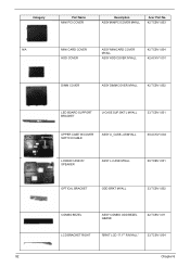
... Name MINI PCI COVER Description ASSY MINIPCI COVER MYALL Acer Part No. 42.TCBV1.003 N/A MINI CARD COVER ASSY MINICARD COVER 42.TCBV1.004 MYALL HDD COVER ASSY HDD COVER MYALL 42.ACKV1.001 DIMM COVER ASSY DIMM COVER MYALL 42.TCBV1.002 LED BOARD SUPPORT BRACKET U-CASE SUP. BKT L MYALL 33.TCBV1.001 UPPER CASE W/COVER SWITCH CABLE ASSY...
... Name MINI PCI COVER Description ASSY MINIPCI COVER MYALL Acer Part No. 42.TCBV1.003 N/A MINI CARD COVER ASSY MINICARD COVER 42.TCBV1.004 MYALL HDD COVER ASSY HDD COVER MYALL 42.ACKV1.001 DIMM COVER ASSY DIMM COVER MYALL 42.TCBV1.002 LED BOARD SUPPORT BRACKET U-CASE SUP. BKT L MYALL 33.TCBV1.001 UPPER CASE W/COVER SWITCH CABLE ASSY...

User's Guide - EN
Page 5
... power off the computer normally, press and hold the power button for more than four seconds to shut down the computer by closing the display cover, or by pressing the sleep hotkey + . If you cannot power off , do any cables away from foot traffic. • When unplugging the power cord, do...
... power off the computer normally, press and hold the power button for more than four seconds to shut down the computer by closing the display cover, or by pressing the sleep hotkey + . If you cannot power off , do any cables away from foot traffic. • When unplugging the power cord, do...

User's Guide - EN
Page 19
Acer ePresentation Management Acer ePresentation Management lets you select from two of the most common projector resolutions: XGA and SVGA. Empowering Technology 9 You can also click "Advanced Settings" to: • Set alarms. • Re-load factory defaults. • Select what actions will be taken when the cover is closed, and set passwords for accessing the system after Hibernation or Standby. • View information about Acer ePower Management.
Acer ePresentation Management Acer ePresentation Management lets you select from two of the most common projector resolutions: XGA and SVGA. Empowering Technology 9 You can also click "Advanced Settings" to: • Set alarms. • Re-load factory defaults. • Select what actions will be taken when the cover is closed, and set passwords for accessing the system after Hibernation or Standby. • View information about Acer ePower Management.

User's Guide - EN
Page 26
Note: Do not cover or obstruct the opening of the fan. Houses the computer's Mini PCI card. Locks the battery in position. 16 Base view English # Item 1 Battery release latch 2 Cooling fan 3 Mini PCI card bay 4 Ventilation slots 5 Memory compartment 6 Hard disk bay 7 Battery lock 8 Battery bay Description Releases the battery for removal. Houses the computer's battery pack. Enable the computer to stay cool, even after prolonged use. Houses the computer's hard disk (secured with screws). Helps keep the computer cool. Houses the computer's main memory.
Note: Do not cover or obstruct the opening of the fan. Houses the computer's Mini PCI card. Locks the battery in position. 16 Base view English # Item 1 Battery release latch 2 Cooling fan 3 Mini PCI card bay 4 Ventilation slots 5 Memory compartment 6 Hard disk bay 7 Battery lock 8 Battery bay Description Releases the battery for removal. Houses the computer's battery pack. Enable the computer to stay cool, even after prolonged use. Houses the computer's hard disk (secured with screws). Helps keep the computer cool. Houses the computer's main memory.

User's Guide - EN
Page 31
Caps Lock Num Lock Lights up when Caps Lock is activated. Battery Indicates the computer's batttery status. Wireless LAN Indicates the status of Bluetooth communication. Bluetooth Indicates the status of wireless LAN communication. Lights up . Power Indicates the computer's power status. Icon Function HDD Description Indicates when the hard disk drive is closed up when Num Lock is activated. 21 Indicators The computer has serveral easy-to-read status indicators: English The front panel indicators are visible even when the computer cover is active.
Caps Lock Num Lock Lights up when Caps Lock is activated. Battery Indicates the computer's batttery status. Wireless LAN Indicates the status of Bluetooth communication. Bluetooth Indicates the status of wireless LAN communication. Lights up . Power Indicates the computer's power status. Icon Function HDD Description Indicates when the hard disk drive is closed up when Num Lock is activated. 21 Indicators The computer has serveral easy-to-read status indicators: English The front panel indicators are visible even when the computer cover is active.

User's Guide - EN
Page 47
...get in the flap located inside the front cover of the ITW passport. If the country you are there to provide the following information available when you call . Our worldwide network of service centers are traveling in does not have an Acer-authorized ITW service site, you can reduce... the screen (or the number and sequence in this passport thoroughly. An ITW passport comes with our offices worldwide. Please consult http://global.acer.com. You are error messages or beeps reported by an International Travelers Warranty (ITW) that gives you security and peace of mind when ...
...get in the flap located inside the front cover of the ITW passport. If the country you are there to provide the following information available when you call . Our worldwide network of service centers are traveling in does not have an Acer-authorized ITW service site, you can reduce... the screen (or the number and sequence in this passport thoroughly. An ITW passport comes with our offices worldwide. Please consult http://global.acer.com. You are error messages or beeps reported by an International Travelers Warranty (ITW) that gives you security and peace of mind when ...

User's Guide - EN
Page 57
...are ready to use the computer again, unlatch and open the display; then press and release the power button. Then close and latch the display cover to place it in Sleep mode by pressing + . To bring the computer out of Sleep mode, open files. 2 Remove any open the...display; When you are taking the computer to a client's office or a different building, you may choose to shut down the computer. 4 Close the display cover. 5 Disconnect the cord from the AC adapter. 6 Disconnect the keyboard, pointing device, printer, external monitor and other external devices. 7 Disconnect the Kensington ...
...are ready to use the computer again, unlatch and open the display; then press and release the power button. Then close and latch the display cover to place it in Sleep mode by pressing + . To bring the computer out of Sleep mode, open files. 2 Remove any open the...display; When you are taking the computer to a client's office or a different building, you may choose to shut down the computer. 4 Close the display cover. 5 Disconnect the cord from the AC adapter. 6 Disconnect the keyboard, pointing device, printer, external monitor and other external devices. 7 Disconnect the Kensington ...

User's Guide - EN
Page 58
...not need to bring to meetings If your desktop, follow these steps to the top cover of time. What to bring anything with you other than your computer. Press + or close the display cover whenever you are not actively using the computer. Preparing the computer After disconnecting the ...computer from sliding around and cushion it if it should fall. If the power indicator is off . Pressure against the top cover can prevent the computer from your meeting room. To resume, open the display (if closed), then press and release the power button. Failure...
...not need to bring to meetings If your desktop, follow these steps to the top cover of time. What to bring anything with you other than your computer. Press + or close the display cover whenever you are not actively using the computer. Preparing the computer After disconnecting the ...computer from sliding around and cushion it if it should fall. If the power indicator is off . Pressure against the top cover can prevent the computer from your meeting room. To resume, open the display (if closed), then press and release the power button. Failure...


