Acer Aspire 8935G Series Service Guide
Page 7
...Basics 11 Using the Keyboard 12 Key Types 12 Windows Keys 13 System Hotkeys 14 Using the System Utilities 15 Acer GridVista (dual-display compatible 15 Hardware Specifications and Configurations 16 System Utilities 35 BIOS Setup Utility 35 Navigating the... Utility 46 Remove HDD/BIOS Password Utilities 47 Machine Disassembly and Replacement 53 Disassembly Requirements 53 General Information 54 Pre-disassembly Instructions 54 Disassembly Process 54 External Module Disassembly Process 55 External Modules Disassembly Flowchart 55 Removing the Battery Pack 56 Removing the ...
...Basics 11 Using the Keyboard 12 Key Types 12 Windows Keys 13 System Hotkeys 14 Using the System Utilities 15 Acer GridVista (dual-display compatible 15 Hardware Specifications and Configurations 16 System Utilities 35 BIOS Setup Utility 35 Navigating the... Utility 46 Remove HDD/BIOS Password Utilities 47 Machine Disassembly and Replacement 53 Disassembly Requirements 53 General Information 54 Pre-disassembly Instructions 54 Disassembly Process 54 External Module Disassembly Process 55 External Modules Disassembly Flowchart 55 Removing the Battery Pack 56 Removing the ...
Acer Aspire 8935G Series Service Guide
Page 8
... Thermal Module 111 Removing the Graphics Card Heatsink 112 Removing the Graphics Card 113 Removing the CPU 114 LCD Module Disassembly Process 115 Standard Bezel LCD Module Disassembly Flowchart 115 Removing the Standard LCD Bezel 116 Removing the LCD Panel 119 Removing the Camera Board 121 Removing the ...LCD Brackets and FPC Cable 122 Flush Bezel LCD Module Disassembly Flowchart 124 Removing the Flush LCD Bezel Cap 125 Removing the Flush LCD Bezel 127 Removing the LCD Panel 129 Removing the Camera ...
... Thermal Module 111 Removing the Graphics Card Heatsink 112 Removing the Graphics Card 113 Removing the CPU 114 LCD Module Disassembly Process 115 Standard Bezel LCD Module Disassembly Flowchart 115 Removing the Standard LCD Bezel 116 Removing the LCD Panel 119 Removing the Camera Board 121 Removing the ...LCD Brackets and FPC Cable 122 Flush Bezel LCD Module Disassembly Flowchart 124 Removing the Flush LCD Bezel Cap 125 Removing the Flush LCD Bezel 127 Removing the LCD Panel 129 Removing the Camera ...

Acer Aspire 8935G Series Service Guide
Page 63
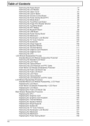
... Replacement Chapter 3 This chapter contains step-by-step procedures on how to avoid mismatch when putting back the components. Disassembly Requirements To disassemble the computer, you need the following tools: • Wrist grounding strap and conductive mat for preventing electrostatic discharge • Flat screwdriver • Philips screwdriver • ...
... Replacement Chapter 3 This chapter contains step-by-step procedures on how to avoid mismatch when putting back the components. Disassembly Requirements To disassemble the computer, you need the following tools: • Wrist grounding strap and conductive mat for preventing electrostatic discharge • Flat screwdriver • Philips screwdriver • ...
Acer Aspire 8935G Series Service Guide
Page 64
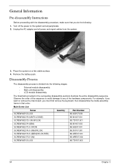
... frame in that you do the following stages: • External module disassembly • Main unit disassembly • LCD module disassembly The flowcharts provided in the succeeding disassembly sections illustrate the entire disassembly sequence. Remove the battery pack. Main Screw List Screw Quantity Part Number... all power and signal cables from the system. 3. Turn off the power to any of the hardware components. Disassembly Process The disassembly process is divided into the following : 1. Unplug the AC adapter and all peripherals. 2. Place the system on a flat, ...
... frame in that you do the following stages: • External module disassembly • Main unit disassembly • LCD module disassembly The flowcharts provided in the succeeding disassembly sections illustrate the entire disassembly sequence. Remove the battery pack. Main Screw List Screw Quantity Part Number... all power and signal cables from the system. 3. Turn off the power to any of the hardware components. Disassembly Process The disassembly process is divided into the following : 1. Unplug the AC adapter and all peripherals. 2. Place the system on a flat, ...
Acer Aspire 8935G Series Service Guide
Page 65
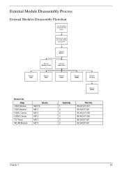
External Module Disassembly Process External Modules Disassembly Flowchart Turn off system and peripherals power Disconnect power and signal cables from system Rem ove Battery Rem ove Dummy Cards Rem ove Lower Door Rem ove ODD Rem ove HDD1 Rem ove HDD2 Rem ove DIMMs Rem ove TV Tuner Screw List Step ODD Module ODD Bracket HDD1 Carrier HDD2 Carrier TV Tuner WLAN Module Screw M2.5*4 M2*3 M3*3 M3*3 M2*3 M2*3 Rem ove WLAN Quantity 1 2 2 2 2 2 Part No. 86.D01V7.001 86.S0207.001 86.A03V7.006 86.A03V7.006 86.S0207.001 86.S0207.001 Chapter 3 55
External Module Disassembly Process External Modules Disassembly Flowchart Turn off system and peripherals power Disconnect power and signal cables from system Rem ove Battery Rem ove Dummy Cards Rem ove Lower Door Rem ove ODD Rem ove HDD1 Rem ove HDD2 Rem ove DIMMs Rem ove TV Tuner Screw List Step ODD Module ODD Bracket HDD1 Carrier HDD2 Carrier TV Tuner WLAN Module Screw M2.5*4 M2*3 M3*3 M3*3 M2*3 M2*3 Rem ove WLAN Quantity 1 2 2 2 2 2 Part No. 86.D01V7.001 86.S0207.001 86.A03V7.006 86.A03V7.006 86.S0207.001 86.S0207.001 Chapter 3 55

Acer Aspire 8935G Series Service Guide
Page 71
NOTE: Remove the left side screw first during disassembly. Insert a pin in the eject hole of the ODD to release the ODD cover and remove. 5. Step ODD Bracket Size M2*3 Quantity 2 6. Chapter 3 61 Press down on the locking catch to eject the ODD tray. Remove the two screws securing the ODD Bracket and remove the ODD bracket from the module. Screw Type 7.
NOTE: Remove the left side screw first during disassembly. Insert a pin in the eject hole of the ODD to release the ODD cover and remove. 5. Step ODD Bracket Size M2*3 Quantity 2 6. Chapter 3 61 Press down on the locking catch to eject the ODD tray. Remove the two screws securing the ODD Bracket and remove the ODD bracket from the module. Screw Type 7.

Acer Aspire 8935G Series Service Guide
Page 81
Main Unit Disassembly Process Upper Cover Disassembly Flowchart Remove External Modules before proceeding Remove Keyboard Remove Switch Cover Remove Power Board Remove LCD Module Remove Upper Cover Lower Cover (see page 99) ...
Main Unit Disassembly Process Upper Cover Disassembly Flowchart Remove External Modules before proceeding Remove Keyboard Remove Switch Cover Remove Power Board Remove LCD Module Remove Upper Cover Lower Cover (see page 99) ...
Acer Aspire 8935G Series Service Guide
Page 82
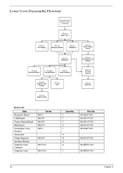
Lower Cover Disassembly Flowchart Remove External Modules before proceeding Rem ove Upper Cover Rem ove RTC Battery Rem ove Bluetooth Module Rem ove USB Board Rem ove Power ...
Lower Cover Disassembly Flowchart Remove External Modules before proceeding Rem ove Upper Cover Rem ove RTC Battery Rem ove Bluetooth Module Rem ove USB Board Rem ove Power ...

Acer Aspire 8935G Series Service Guide
Page 125
... Bezel with the Standard Bezel detailed below. The following sections detail the two distinct procedures, beginning with glass panel LCD Module. Standard Bezel LCD Module Disassembly Flowchart Remove LCD Panel from Main Unit before proceeding Rem ove LCD Bezel Rem ove LCD Panel Rem ove Camera Module Rem ove LCD FPC...
... Bezel with the Standard Bezel detailed below. The following sections detail the two distinct procedures, beginning with glass panel LCD Module. Standard Bezel LCD Module Disassembly Flowchart Remove LCD Panel from Main Unit before proceeding Rem ove LCD Bezel Rem ove LCD Panel Rem ove Camera Module Rem ove LCD FPC...
Acer Aspire 8935G Series Service Guide
Page 207
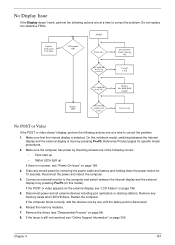
... Information" on this notebook model, switching between the internal display and the external display is selected. Restart the computer. Power On? goto no power, see "Disassembly Process" on page 199. 5. DDRRAM module OK? No Ext. Make sure that the internal display is by pressing Fn+F5. Reference Product pages for 10...
... Information" on this notebook model, switching between the internal display and the external display is selected. Restart the computer. Power On? goto no power, see "Disassembly Process" on page 199. 5. DDRRAM module OK? No Ext. Make sure that the internal display is by pressing Fn+F5. Reference Product pages for 10...
Acer Aspire 8935G Series Service Guide
Page 208
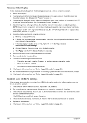
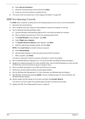
..." on page 54. 5. See "Disassembly Process" on page 54. 3. Random Loss of BIOS Settings If the computer is experiencing intermittent loss of BIOS information, perform the following actions one at a ... correct the problem. 1. Abnormal Video Display If video displays abnormally, perform the following actions one at a time to correct the problem. 1. Reboot the computer. 2. See "Disassembly Process" on adjusting settings. See the User Manual for instructions on page 54. 4. Check the display resolution is virus free. 3. Roll back the video driver...
..." on page 54. 5. See "Disassembly Process" on page 54. 3. Random Loss of BIOS Settings If the computer is experiencing intermittent loss of BIOS information, perform the following actions one at a ... correct the problem. 1. Abnormal Video Display If video displays abnormally, perform the following actions one at a time to correct the problem. 1. Reboot the computer. 2. See "Disassembly Process" on adjusting settings. See the User Manual for instructions on page 54. 4. Check the display resolution is virus free. 3. Roll back the video driver...
Acer Aspire 8935G Series Service Guide
Page 214
... associated software. 8. c. Select Repair your computer. The System Recovery Options screen displays. h. Restore system and file settings from a known good date using up microphone. See "Disassembly Process" on page 305. b. Run a complete virus scan using System Restore. Run the Windows Vista Startup Repair Utility: a. Run the Windows Disk Defragmenter. If the...
... associated software. 8. c. Select Repair your computer. The System Recovery Options screen displays. h. Restore system and file settings from a known good date using up microphone. See "Disassembly Process" on page 305. b. Run a complete virus scan using System Restore. Run the Windows Vista Startup Repair Utility: a. Run the Windows Disk Defragmenter. If the...
Acer Aspire 8935G Series Service Guide
Page 317
...) 134 Common Problems 196 CPU 114 Replacing 148 D DIMM Modules Removing 66 Display 4 E Express Dummy Card Removing 57 External Module Disassembly Flowchart 55 Index F Features 1 Flash Utility 43 Flush Bezel Disassembly Flowchart 124 Flush LCD Bezel Removing 127 FP Reader Bracket Removing 93, 168 FPC Cable Removing (flush) 132 Removing (standard) 122...
...) 134 Common Problems 196 CPU 114 Replacing 148 D DIMM Modules Removing 66 Display 4 E Express Dummy Card Removing 57 External Module Disassembly Flowchart 55 Index F Features 1 Flash Utility 43 Flush Bezel Disassembly Flowchart 124 Flush LCD Bezel Removing 127 FP Reader Bracket Removing 93, 168 FPC Cable Removing (flush) 132 Removing (standard) 122...
Acer Aspire 8935G Series Service Guide
Page 318
...standard) 122 Replacing (flush) 140 Replacing (standard) 134 LCD Cable Replacing (flush) 140 Replacing (standard) 134 LCD Failure 199 LCD Module Disassembly 115 Removing 78 LCD Module Reassembly Procedure 134 LCD Panel Removing (flush) 129 Removing (standard) 119 Replacing (flush) 140 Replacing (standard)... 134 Left Hinge Support Removing 109, 153 Lower Cover Disassembly Flowchart 72 Lower Covers Removing 59 M Main Module Reassembly Procedure 148 Main Unit Disassembly Flowchart 71 Mainboard Removing 103, 158 308 Replacing 157 Media Board Removing 89, 171 Memory...
...standard) 122 Replacing (flush) 140 Replacing (standard) 134 LCD Cable Replacing (flush) 140 Replacing (standard) 134 LCD Failure 199 LCD Module Disassembly 115 Removing 78 LCD Module Reassembly Procedure 134 LCD Panel Removing (flush) 129 Removing (standard) 119 Replacing (flush) 140 Replacing (standard)... 134 Left Hinge Support Removing 109, 153 Lower Cover Disassembly Flowchart 72 Lower Covers Removing 59 M Main Module Reassembly Procedure 148 Main Unit Disassembly Flowchart 71 Mainboard Removing 103, 158 308 Replacing 157 Media Board Removing 89, 171 Memory...

Acer Aspire 8935G Series Service Guide
Page 319
Speaker Module Removing 110, 152 Standard Bezel Disassembly Flowchart 115 Standard LCD Bezel Removing 116 Subwoofer Removing 107, 154 Switch Cover Removing 75, 184 System Block Diagram 4 T Test Compatible Components 271 Thermal Grease ... On 196 TouchPad 201 TV Tuner Antenna Removing 106, 156 TV Tuner Module Removing 67, 189 U Undetermined Problems 206 Upper Cover Removing 81 Upper Cover Disassembly Flowchart 71 USB Board Removing 100, 160 utility BIOS 35-43 V Volume Control Board Removing 86, 173 W Windows 2000 Environment Test 272 WLAN Board 69...
Speaker Module Removing 110, 152 Standard Bezel Disassembly Flowchart 115 Standard LCD Bezel Removing 116 Subwoofer Removing 107, 154 Switch Cover Removing 75, 184 System Block Diagram 4 T Test Compatible Components 271 Thermal Grease ... On 196 TouchPad 201 TV Tuner Antenna Removing 106, 156 TV Tuner Module Removing 67, 189 U Undetermined Problems 206 Upper Cover Removing 81 Upper Cover Disassembly Flowchart 71 USB Board Removing 100, 160 utility BIOS 35-43 V Volume Control Board Removing 86, 173 W Windows 2000 Environment Test 272 WLAN Board 69...


