Acer Aspire 8935G Notebook Series Start Guide
Page 11
11 English Specifications Operating • system Platform • System memory • • Display • • TV-tuner • Graphics • • Audio • • • • • • Storage • subsystem • • Genuine Windows Vista® ... sound output High-definition audio support S/PDIF (Sony/Philips Digital Interface) support for digital speakers MS-Sound compatible Acer Purezone technology with two built-in -1 card reader layer drive • Blu-ray Disc™/DVD-Super Multi double-layer drive* • DVD-Super...
11 English Specifications Operating • system Platform • System memory • • Display • • TV-tuner • Graphics • • Audio • • • • • • Storage • subsystem • • Genuine Windows Vista® ... sound output High-definition audio support S/PDIF (Sony/Philips Digital Interface) support for digital speakers MS-Sound compatible Acer Purezone technology with two built-in -1 card reader layer drive • Blu-ray Disc™/DVD-Super Multi double-layer drive* • DVD-Super...
Acer Aspire 8935G Series Service Guide
Page 8
... 107 Removing the Hinge Supports 109 Removing the Speaker Module 110 Removing the Thermal Module 111 Removing the Graphics Card Heatsink 112 Removing the Graphics Card 113 Removing the CPU 114 LCD Module Disassembly Process 115 Standard Bezel LCD Module Disassembly Flowchart 115 Removing ...144 Replacing the Flush LCD Bezel Cap 146 Main Module Reassembly Procedure 148 Replacing the CPU 148 Replacing the Graphics Card 149 Replacing the Graphics Card Heatsink 150 Replacing the Thermal Module 151 Replacing the Speaker Module 152 Replacing the Hinge Supports 153 Replacing the...
... 107 Removing the Hinge Supports 109 Removing the Speaker Module 110 Removing the Thermal Module 111 Removing the Graphics Card Heatsink 112 Removing the Graphics Card 113 Removing the CPU 114 LCD Module Disassembly Process 115 Standard Bezel LCD Module Disassembly Flowchart 115 Removing ...144 Replacing the Flush LCD Bezel Cap 146 Main Module Reassembly Procedure 148 Replacing the CPU 148 Replacing the Graphics Card 149 Replacing the Graphics Card Heatsink 150 Replacing the Thermal Module 151 Replacing the Speaker Module 152 Replacing the Hinge Supports 153 Replacing the...

Acer Aspire 8935G Series Service Guide
Page 11
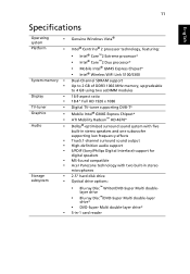
...to 4 GB using two soDIMM modules Display • • • 18.47" TFT LCD Resolution: 1920 x 1080 Full HD 16:9 aspect ratio Graphics Mobile Intel® GM45 Express Chipset* ATI Mobility Radeon™ HD 4670* ATI Mobility Radeon™ HD 4650* NVIDIA® GeForce® GT 130M... drive options: • Blu-ray Disc™ /DVD-Super Multi double-layer drive* • DVD-Super Multi double-layer drive* • 6-in-1 card reader (SD/MMC/MMC4.0/MS/MS Pro/XD) Chapter 1 1 System Specifications Chapter 1 Features Below is a brief summary of DDR3 1066 MHz memory, upgradeable ...
...to 4 GB using two soDIMM modules Display • • • 18.47" TFT LCD Resolution: 1920 x 1080 Full HD 16:9 aspect ratio Graphics Mobile Intel® GM45 Express Chipset* ATI Mobility Radeon™ HD 4670* ATI Mobility Radeon™ HD 4650* NVIDIA® GeForce® GT 130M... drive options: • Blu-ray Disc™ /DVD-Super Multi double-layer drive* • DVD-Super Multi double-layer drive* • 6-in-1 card reader (SD/MMC/MMC4.0/MS/MS Pro/XD) Chapter 1 1 System Specifications Chapter 1 Features Below is a brief summary of DDR3 1066 MHz memory, upgradeable ...
Acer Aspire 8935G Series Service Guide
Page 82
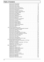
...ove Speaker Module Rem ove Thermal Module Rem ove Hinge Supports Rem ove TV Tuner Antenna Rem ove Graphics Card Heatsink Rem ove CPU Rem ove Subwoofer Rem ove Graphics Card Screw List Step Bluetooth Board USB Board Power Saving Board Mainboard Kensington Lock Bracket Subwoofer Hinge Supports ...Speaker Module Graphics Card Heatsink Graphics Card Screw M2*3 M2.5*4 M2.5*4 M2.5*4 M2*3 M2.5*4 M2.5*6.5 M2.5*6.5 Quantity 1 1 1 3 1 4 6 6 2 1 Part No. 86.S0207.001 86.D01V7.001 86....
...ove Speaker Module Rem ove Thermal Module Rem ove Hinge Supports Rem ove TV Tuner Antenna Rem ove Graphics Card Heatsink Rem ove CPU Rem ove Subwoofer Rem ove Graphics Card Screw List Step Bluetooth Board USB Board Power Saving Board Mainboard Kensington Lock Bracket Subwoofer Hinge Supports ...Speaker Module Graphics Card Heatsink Graphics Card Screw M2*3 M2.5*4 M2.5*4 M2.5*4 M2*3 M2.5*4 M2.5*6.5 M2.5*6.5 Quantity 1 1 1 3 1 4 6 6 2 1 Part No. 86.S0207.001 86.D01V7.001 86....

Acer Aspire 8935G Series Service Guide
Page 122
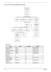
Remove the two screws (in reverse numerical order from the Graphics Card as shown. Removing the Graphics Card Heatsink 1. Lift the heatsink away from 2 to 1) securing the Graphics Card Heatsink to the Mainboard. 2 1 Step Graphics Card Heatsink Size M2.5*6.5 Quantity 2 3. Screw Type 112 Chapter 3 See "Removing the Thermal Module" on page 111. 2.
Remove the two screws (in reverse numerical order from the Graphics Card as shown. Removing the Graphics Card Heatsink 1. Lift the heatsink away from 2 to 1) securing the Graphics Card Heatsink to the Mainboard. 2 1 Step Graphics Card Heatsink Size M2.5*6.5 Quantity 2 3. Screw Type 112 Chapter 3 See "Removing the Thermal Module" on page 111. 2.

Acer Aspire 8935G Series Service Guide
Page 123
Remove the Graphics Card from the Mainboard connector. Remove the single screw securing the Graphics Card to the Mainboard. Screw Type Chapter 3 113 See "Removing the Graphics Card Heatsink" on page 112. 2. Step Graphics Card Size M2.5*6.5 Quantity 1 3. Removing the Graphics Card 1.
Remove the Graphics Card from the Mainboard connector. Remove the single screw securing the Graphics Card to the Mainboard. Screw Type Chapter 3 113 See "Removing the Graphics Card Heatsink" on page 112. 2. Step Graphics Card Size M2.5*6.5 Quantity 1 3. Removing the Graphics Card 1.

Acer Aspire 8935G Series Service Guide
Page 159
Replacing the Graphics Card 3. Insert the single screw to secure the Graphics Card to the Mainboard. Insert the Graphics Card into the Mainboard connector. 4. Step Graphics Card Size M2.5*6.5 Quantity 1 Screw Type Chapter 3 149
Replacing the Graphics Card 3. Insert the single screw to secure the Graphics Card to the Mainboard. Insert the Graphics Card into the Mainboard connector. 4. Step Graphics Card Size M2.5*6.5 Quantity 1 Screw Type Chapter 3 149

Acer Aspire 8935G Series Service Guide
Page 160
...Honeywell PCM45F-SP • ShinEtsu 7762 The following thermal pads are in numerical order from 1 to 2) to secure the Graphics Card Heatsink to spread the grease manually, the force used during the installation of the Thermal Module is no need to the Mainboard. 2 ...Step Graphics Card Heatsink Size M2.5*6.5 1 Quantity 2 Screw Type 150 Chapter 3 Replacing the Graphics Card Heatsink IMPORTANT: Apply a suitable thermal grease and ensure all traces of thermal grease from the Graphics Card as shown. 4. Remove all heat pads are approved ...
...Honeywell PCM45F-SP • ShinEtsu 7762 The following thermal pads are in numerical order from 1 to 2) to secure the Graphics Card Heatsink to spread the grease manually, the force used during the installation of the Thermal Module is no need to the Mainboard. 2 ...Step Graphics Card Heatsink Size M2.5*6.5 1 Quantity 2 Screw Type 150 Chapter 3 Replacing the Graphics Card Heatsink IMPORTANT: Apply a suitable thermal grease and ensure all traces of thermal grease from the Graphics Card as shown. 4. Remove all heat pads are approved ...

Acer Aspire 8935G Series Service Guide
Page 226
Description 1 Mainboard 2 Dummy New Card 3 Dummy SD Card 4 Graphics Card 5 Thermal Module 6 Memory 7 Lower Cover 8 HDD2 6 78 Acer P/N TBD 42.PDA07.003 42.PDA07.004 VG.M9606.004 60.PDA07.007 KN.2GB04.004 60.PDA07.002 KH.16007.019 No. Description 9 Lower Door 10 HDD1 11 Battery 12 ODD 13 Bluetooth 14 Upper Cover 15 Keyboard 16 Switch Cover 11 10 9 Acer P/N 42.PDA07.002 KH.16007.019 BT.00803.024 6M.PDA07.001 BT.21100.005 60.PDA07.001 KB.I170A.005 42.PDA07.001 216 Chapter 6 Acer SM80 Exploded Diagrams Main Chassis 16 15 1 14 2 13 3 4 12 5 No.
Description 1 Mainboard 2 Dummy New Card 3 Dummy SD Card 4 Graphics Card 5 Thermal Module 6 Memory 7 Lower Cover 8 HDD2 6 78 Acer P/N TBD 42.PDA07.003 42.PDA07.004 VG.M9606.004 60.PDA07.007 KN.2GB04.004 60.PDA07.002 KH.16007.019 No. Description 9 Lower Door 10 HDD1 11 Battery 12 ODD 13 Bluetooth 14 Upper Cover 15 Keyboard 16 Switch Cover 11 10 9 Acer P/N 42.PDA07.002 KH.16007.019 BT.00803.024 6M.PDA07.001 BT.21100.005 60.PDA07.001 KB.I170A.005 42.PDA07.001 216 Chapter 6 Acer SM80 Exploded Diagrams Main Chassis 16 15 1 14 2 13 3 4 12 5 No.
Acer Aspire 8935G Series Service Guide
Page 317
... Bezel Removing 127 FP Reader Bracket Removing 93, 168 FPC Cable Removing (flush) 132 Removing (standard) 122 FRU (Field Replaceable Unit) List 215 G Graphics Card Removing 113, 149 Graphics Card Heatsink Removing 112, 150 H HDD Cover Removing 59 HDD1 Removing 62 HDD2 Removing 64 Hinge Supports Removing 109, 153 Hot Keys 12 I Indicators 11...
... Bezel Removing 127 FP Reader Bracket Removing 93, 168 FPC Cable Removing (flush) 132 Removing (standard) 122 FRU (Field Replaceable Unit) List 215 G Graphics Card Removing 113, 149 Graphics Card Heatsink Removing 112, 150 H HDD Cover Removing 59 HDD1 Removing 62 HDD2 Removing 64 Hinge Supports Removing 109, 153 Hot Keys 12 I Indicators 11...


