
Acer Aspire 6530 Notebook Series Start Guide
Page 5
... like a computer mouse. 10 VOL+/ Volume Up/ VOL- Volume Down Increase system volume/decrease system volume. 11 Acer MediaTouch For use with Acer Arcade and other keys media playing programs. 12 Easy-launch Buttons for launching frequently used buttons programs. Please refer to...show the status of the computer's functions and components. 5 English # Icon Item Description 3 Display screen Also called Liquid-Crystal Display (LCD), displays computer output. 4 Power button Turns the computer on and off. 5 Status indicators Light-Emitting Diodes (LEDs) that light up...
... like a computer mouse. 10 VOL+/ Volume Up/ VOL- Volume Down Increase system volume/decrease system volume. 11 Acer MediaTouch For use with Acer Arcade and other keys media playing programs. 12 Easy-launch Buttons for launching frequently used buttons programs. Please refer to...show the status of the computer's functions and components. 5 English # Icon Item Description 3 Display screen Also called Liquid-Crystal Display (LCD), displays computer output. 4 Power button Turns the computer on and off. 5 Status indicators Light-Emitting Diodes (LEDs) that light up...

Acer Aspire 6530 Notebook Series Start Guide
Page 7
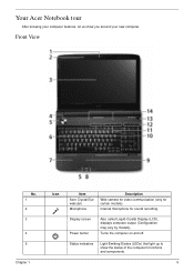
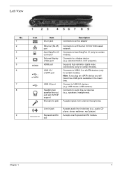
... have three USB ports available in jack ExpressCard/54 slot Connects to an Ethernet 10/100/1000based network. Connects to Acer EasyPort IV (only for certain models). Supports high definition digital video connections (only for certain models). Accepts audio line...-in jack Description Connects to USB 2.0 devices (e.g., USB mouse, USB camera). Connects to a display device (e.g., external monitor, LCD projector). 7 Left view English # Icon 1 2 3 4 5 HDMI 6 7 8 9 Item DC-in devices (e.g., audio CD player, stereo walkman, mp3 ...
... have three USB ports available in jack ExpressCard/54 slot Connects to an Ethernet 10/100/1000based network. Connects to Acer EasyPort IV (only for certain models). Supports high definition digital video connections (only for certain models). Accepts audio line...-in jack Description Connects to USB 2.0 devices (e.g., USB mouse, USB camera). Connects to a display device (e.g., external monitor, LCD projector). 7 Left view English # Icon 1 2 3 4 5 HDMI 6 7 8 9 Item DC-in devices (e.g., audio CD player, stereo walkman, mp3 ...

Aspire 6530/6530G Quick Guide
Page 8
...81 Removing the Inverter Board 84 Removing the Camera Module 85 Removing the LCD Panel 86 Removing the LCD Brackets and FPC Cable 87 LCD Module Reassembly Procedure 89 Replacing the LCD Panel 89 Replacing the LCD Bezel 93 Main Module Reassembly Procedure 95 Replacing the CPU 95 Replacing the... the Bluetooth Board 99 Replacing the Modem Module 99 Replacing the Finger Print Reader 100 Replacing the Upper Cover 102 Replacing the LCD Module 104 Replacing the Speaker Module 107 Replacing the Keyboard 107 Replacing the Power Board 108 Replacing the Switch Cover 109 Replacing ...
...81 Removing the Inverter Board 84 Removing the Camera Module 85 Removing the LCD Panel 86 Removing the LCD Brackets and FPC Cable 87 LCD Module Reassembly Procedure 89 Replacing the LCD Panel 89 Replacing the LCD Bezel 93 Main Module Reassembly Procedure 95 Replacing the CPU 95 Replacing the... the Bluetooth Board 99 Replacing the Modem Module 99 Replacing the Finger Print Reader 100 Replacing the Upper Cover 102 Replacing the LCD Module 104 Replacing the Speaker Module 107 Replacing the Keyboard 107 Replacing the Power Board 108 Replacing the Switch Cover 109 Replacing ...
Aspire 6530/6530G Quick Guide
Page 9
... Clearing Password Check 147 BIOS Recovery by Crisis Disk 148 FRU (Field Replaceable Unit) List 149 Aspire 6530 Exploded Diagrams 150 Main Module 150 LCD Module 151 Aspire 6530 FRU List 152 Screw List 161 Model Definition and Configuration 164 Aspire 6530 Series 164 Test Compatible Components 201 Microsoft® Windows® Vista Environment Test 202 Peripheral...
... Clearing Password Check 147 BIOS Recovery by Crisis Disk 148 FRU (Field Replaceable Unit) List 149 Aspire 6530 Exploded Diagrams 150 Main Module 150 LCD Module 151 Aspire 6530 FRU List 152 Screw List 161 Model Definition and Configuration 164 Aspire 6530 Series 164 Test Compatible Components 201 Microsoft® Windows® Vista Environment Test 202 Peripheral...
Aspire 6530/6530G Quick Guide
Page 15
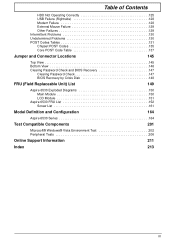
Front View No. 1 2 3 4 5 Chapter 1 Icon Item Acer Crystal Eye webcam Microphone Description Web camera for video communication (only for sound recording. Turns the computer on and off. Internal microphone for certain models). ... you around your computer features, let us show the status of the computer's functions and components. 5 Display screen Power button Also called Liquid-Crystal Display (LCD), displays computer output (Configuration may vary by models). Your Acer Notebook tour After knowing your new computer.
Front View No. 1 2 3 4 5 Chapter 1 Icon Item Acer Crystal Eye webcam Microphone Description Web camera for video communication (only for sound recording. Turns the computer on and off. Internal microphone for certain models). ... you around your computer features, let us show the status of the computer's functions and components. 5 Display screen Power button Also called Liquid-Crystal Display (LCD), displays computer output (Configuration may vary by models). Your Acer Notebook tour After knowing your new computer.
Aspire 6530/6530G Quick Guide
Page 17
...-based network. Line-in jack ExpressCard/54 slot Accepts audio line-in jack Description Connects to an AC adapter Ethernet (RJ-45) port Acer EasyPort IV connector External display (VGA) port HDMI port USB 2.0 / e SATA port USB 2.0 port Headphones/ speaker/line-out jack with...plug an eSATA device you will have three USB ports available in the mean time. Connect to Acer EasyPort IV (only for certain models). Chapter 1 7 Connects to a display device (e.g. external monitor, LCD projector). USB mouse, USB camera). Accepts inputs from external microphones. Connects to audio line-out ...
...-based network. Line-in jack ExpressCard/54 slot Accepts audio line-in jack Description Connects to an AC adapter Ethernet (RJ-45) port Acer EasyPort IV connector External display (VGA) port HDMI port USB 2.0 / e SATA port USB 2.0 port Headphones/ speaker/line-out jack with...plug an eSATA device you will have three USB ports available in the mean time. Connect to Acer EasyPort IV (only for certain models). Chapter 1 7 Connects to a display device (e.g. external monitor, LCD projector). USB mouse, USB camera). Accepts inputs from external microphones. Connects to audio line-out ...
Aspire 6530/6530G Quick Guide
Page 34
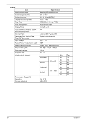
LCD 16" Item Specification Vendor/model name Samsung LTN160HT01-A02 Screen Diagonal (mm) 406.4 (16.0") Active Area (mm) 353.28 (H) x 198.72 (V) Display resolution (pixels) 1920 x ...
LCD 16" Item Specification Vendor/model name Samsung LTN160HT01-A02 Screen Diagonal (mm) 406.4 (16.0") Active Area (mm) 353.28 (H) x 198.72 (V) Display resolution (pixels) 1920 x ...
Aspire 6530/6530G Quick Guide
Page 52
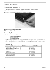
... system. 3. For example, if you want to remove the main board, you do the following stages: • External module disassembly • Main unit disassembly • LCD module disassembly The flowcharts provided in that you must first remove the keyboard, then disassemble the inside assembly frame in the succeeding disassembly sections illustrate...
... system. 3. For example, if you want to remove the main board, you do the following stages: • External module disassembly • Main unit disassembly • LCD module disassembly The flowcharts provided in that you must first remove the keyboard, then disassemble the inside assembly frame in the succeeding disassembly sections illustrate...
Aspire 6530/6530G Quick Guide
Page 69
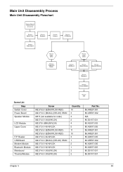
...Disassembly Process Main Unit Disassembly Flowchart Remove External Modules before proceeding Rem ove Switch Cover Rem ove Keyboard Rem ove Antenna Rem ove LCD Module Rem ove Power Board Rem ove Upper Cover Rem ove Fingerprint Reader Rem ove Lower Cover Rem ove USB Board Rem ... Modem Module Rem ove Bluetooth Module Rem ove Mainboard Rem ove Thermal Module Rem ove CPU Screw List Step Switch Cover Power Board Speaker Module LCD Module Upper Cover F/P Reader USB Board Modem Module Bluetooth Module Mainboard Thermal Module Screw M2.5*6.5-I (BZN(NYLOK-RED) M2.0*3.0-I (BKAG) (NYLOK) ...
...Disassembly Process Main Unit Disassembly Flowchart Remove External Modules before proceeding Rem ove Switch Cover Rem ove Keyboard Rem ove Antenna Rem ove LCD Module Rem ove Power Board Rem ove Upper Cover Rem ove Fingerprint Reader Rem ove Lower Cover Rem ove USB Board Rem ... Modem Module Rem ove Bluetooth Module Rem ove Mainboard Rem ove Thermal Module Rem ove CPU Screw List Step Switch Cover Power Board Speaker Module LCD Module Upper Cover F/P Reader USB Board Modem Module Bluetooth Module Mainboard Thermal Module Screw M2.5*6.5-I (BZN(NYLOK-RED) M2.0*3.0-I (BKAG) (NYLOK) ...
Aspire 6530/6530G Quick Guide
Page 70
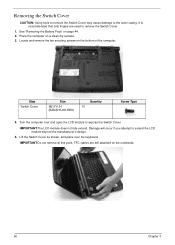
... securing screws on page 44. 2. IMPORTANT:Do not remove at this point. Lift the Switch Cover as shown, and place over and open the LCD module to remove the Switch Cover. 1. Step Switch Cover Size M2.5*6.5-I (BZN(NYLOK-RED) Quantity 10 Screw Type 4. See "Removing the Battery Pack..." on the bottom of the computer. FFC cables are used to expose the Switch Cover. IMPORTANT:The LCD module does not fully extend. It is recommended that only fingers are still attached on a clean dry surface. 3. Turn the computer over the keyboard...
... securing screws on page 44. 2. IMPORTANT:Do not remove at this point. Lift the Switch Cover as shown, and place over and open the LCD module to remove the Switch Cover. 1. Step Switch Cover Size M2.5*6.5-I (BZN(NYLOK-RED) Quantity 10 Screw Type 4. See "Removing the Battery Pack..." on the bottom of the computer. FFC cables are used to expose the Switch Cover. IMPORTANT:The LCD module does not fully extend. It is recommended that only fingers are still attached on a clean dry surface. 3. Turn the computer over the keyboard...

Aspire 6530/6530G Quick Guide
Page 77
Step LCD Module Size M2.5*5-I (BNI)(NYLOK) Quantity 4 Screw Type Chapter 3 67 Remove the four securing screws (two on page 65. 2. See "Removing the Antenna Cables" on each hinge) from the LCD hinges. Disconnect the LCD and Power cables. 3. Disconnect the Antenna cables. Removing the LCD Module 1.
Step LCD Module Size M2.5*5-I (BNI)(NYLOK) Quantity 4 Screw Type Chapter 3 67 Remove the four securing screws (two on page 65. 2. See "Removing the Antenna Cables" on each hinge) from the LCD hinges. Disconnect the LCD and Power cables. 3. Disconnect the Antenna cables. Removing the LCD Module 1.

Aspire 6530/6530G Quick Guide
Page 78
4. Carefully remove the LCD module from the chassis. See "Removing the LCD Module" on the bottom panel. Turn the computer over. Step Upper Cover (Red call out) Upper Cover (Blue call out) Size M2.0*3.0-I-NI-NYLOK 2 Quantity M2.5*6.5-I 11 (BZN(NYLOK-RED) Screw Type 68 Chapter 3 Remove the ten screws on page 67. 2. Removing the Upper Base 1. Remove the LCD module.
4. Carefully remove the LCD module from the chassis. See "Removing the LCD Module" on the bottom panel. Turn the computer over. Step Upper Cover (Red call out) Upper Cover (Blue call out) Size M2.0*3.0-I-NI-NYLOK 2 Quantity M2.5*6.5-I 11 (BZN(NYLOK-RED) Screw Type 68 Chapter 3 Remove the ten screws on page 67. 2. Removing the Upper Base 1. Remove the LCD module.

Aspire 6530/6530G Quick Guide
Page 86
Remove the Bluetooth Module. Disconnect the USB and Bluetooth cables remaining on page 67. 2. Remove the Upper Base. See "Removing the LCD Module" on the mainboard. 6. Remove the LCD Module. Remove the See "Removing the Modem Module" on page 68. 3. Grasp the RJ-11 cable and remove it from the mainboard cable notch as shown. 7. See "Removing the Upper Base" on page 73. 4. Removing the Mainboard 1. Disconnect the Subwoofer cable attached to the mainboard. 76 Chapter 3 See "Removing the Bluetooth Module" on page 74. 5.
Remove the Bluetooth Module. Disconnect the USB and Bluetooth cables remaining on page 67. 2. Remove the Upper Base. See "Removing the LCD Module" on the mainboard. 6. Remove the LCD Module. Remove the See "Removing the Modem Module" on page 68. 3. Grasp the RJ-11 cable and remove it from the mainboard cable notch as shown. 7. See "Removing the Upper Base" on page 73. 4. Removing the Mainboard 1. Disconnect the Subwoofer cable attached to the mainboard. 76 Chapter 3 See "Removing the Bluetooth Module" on page 74. 5.

Aspire 6530/6530G Quick Guide
Page 91
Step LCD Bezel Size M2.5*6.5-I (BZN(NYLOK-RED) Quantity 10 3. Remove the LCD module. Remove the four upper screw caps and screws, and the six remaining lower securing screws. Lift up the bezel, topside first, and remove it from the LCD Module. Screw Type Chapter 3 81 See "Removing the LCD Module" on page 67. 2. Removing the LCD Bezel 1.
Step LCD Bezel Size M2.5*6.5-I (BZN(NYLOK-RED) Quantity 10 3. Remove the LCD module. Remove the four upper screw caps and screws, and the six remaining lower securing screws. Lift up the bezel, topside first, and remove it from the LCD Module. Screw Type Chapter 3 81 See "Removing the LCD Module" on page 67. 2. Removing the LCD Bezel 1.

Aspire 6530/6530G Quick Guide
Page 93
7. Chapter 3 83 Disconnect the Mic cable and remove the LCD bezel.
7. Chapter 3 83 Disconnect the Mic cable and remove the LCD bezel.

Aspire 6530/6530G Quick Guide
Page 94
Remove the LCD Bezel. Disconnect both cables from the LCD Module. 84 Chapter 3 See "Removing the LCD Bezel" on page 81. 2. Remove the Inverter board from the Inverter Board. Removing the Inverter Board 1. NOTE: If you are having difficulty removing the cables, first lift the Inverter Board from the back cover before disconnecting the cables. 3.
Remove the LCD Bezel. Disconnect both cables from the LCD Module. 84 Chapter 3 See "Removing the LCD Bezel" on page 81. 2. Remove the Inverter board from the Inverter Board. Removing the Inverter Board 1. NOTE: If you are having difficulty removing the cables, first lift the Inverter Board from the back cover before disconnecting the cables. 3.

Aspire 6530/6530G Quick Guide
Page 95
Disconnect the Camera Module cable as shown. See "Removing the LCD Bezel" on the ends of the module and pry it away from the cover. Place your finger on page 81. 2. Removing the Camera Module 1. Remove the LCD Bezel. Chapter 3 85 NOTE: If necessary lift the camera module to provide better access to the cables. 3.
Disconnect the Camera Module cable as shown. See "Removing the LCD Bezel" on the ends of the module and pry it away from the cover. Place your finger on page 81. 2. Removing the Camera Module 1. Remove the LCD Bezel. Chapter 3 85 NOTE: If necessary lift the camera module to provide better access to the cables. 3.

Aspire 6530/6530G Quick Guide
Page 96
See "Removing the LCD Bezel" on page 81. 2. Once the panel is upright, lift the panel upwards taking care of the LCD Panel and pivot upwards to a 90 degree angle. 4. Remove the six securing screws from the LCD hinges. Step LCD Panel Size M2.5*2.5-I (NI)(NYLOK) Quantity 6 Screw Type 3. Remove the LCD Bezel. Removing the LCD Panel 1. Grasp the top of the cables located in the hinges. 86 Chapter 3
See "Removing the LCD Bezel" on page 81. 2. Once the panel is upright, lift the panel upwards taking care of the LCD Panel and pivot upwards to a 90 degree angle. 4. Remove the six securing screws from the LCD hinges. Step LCD Panel Size M2.5*2.5-I (NI)(NYLOK) Quantity 6 Screw Type 3. Remove the LCD Bezel. Removing the LCD Panel 1. Grasp the top of the cables located in the hinges. 86 Chapter 3

Aspire 6530/6530G Quick Guide
Page 97
See "Removing the LCD Panel" on a clean surface, and grip the LCD cable by both ends and pull it back. 5. Turn the LCD Panel over on page 86. 2. Chapter 3 87 Dislodge the LCD cable from the left LCD hinge as shown in the following image. 3. Grip the adhesive strip and pull it back. 4. Continue to pull back the LCD cable. Removing the LCD Brackets and FPC Cable 1. Remove the LCD panel.
See "Removing the LCD Panel" on a clean surface, and grip the LCD cable by both ends and pull it back. 5. Turn the LCD Panel over on page 86. 2. Chapter 3 87 Dislodge the LCD cable from the left LCD hinge as shown in the following image. 3. Grip the adhesive strip and pull it back. 4. Continue to pull back the LCD cable. Removing the LCD Brackets and FPC Cable 1. Remove the LCD panel.

Aspire 6530/6530G Quick Guide
Page 98
Remove the LCD brackets by pulling them away from the LCD Panel brackets. Step LCD Brackets Size M2.0*3.0-I (BKAG) (NYLOK) IRON Quantity 8 8. Remove the eight securing screws (four on each side) from the LCD Panel. Screw Type 88 Chapter 3 6. Peel back the adhesive strip holding the cable to the bottom. 7.
Remove the LCD brackets by pulling them away from the LCD Panel brackets. Step LCD Brackets Size M2.0*3.0-I (BKAG) (NYLOK) IRON Quantity 8 8. Remove the eight securing screws (four on each side) from the LCD Panel. Screw Type 88 Chapter 3 6. Peel back the adhesive strip holding the cable to the bottom. 7.


