Aspire 6530/6530G Quick Guide
Page 7
...Launch Buttons 10 Touchpad Basics (with fingerprint reader 11 Using the Keyboard 12 Lock Keys and embedded numeric keypad 12 Windows Keys 13 Hot Keys 14 Special Key 15 Using the System Utilities 16 Acer GridVista (dual-display compatible 16 Hardware Specifications and Configurations 18 ... Flowchart 43 Removing the Battery Pack 44 Removing the SD dummy card 45 Removing the ExpressCard dummy card 46 Removing the Lower Covers 47 Removing the DIMM Modules 48 Removing the VGA Module 49 Removing the TV Tuner Module 50 Removing the Main Hard Disk Drive Module 53 Removing the Optical...
...Launch Buttons 10 Touchpad Basics (with fingerprint reader 11 Using the Keyboard 12 Lock Keys and embedded numeric keypad 12 Windows Keys 13 Hot Keys 14 Special Key 15 Using the System Utilities 16 Acer GridVista (dual-display compatible 16 Hardware Specifications and Configurations 18 ... Flowchart 43 Removing the Battery Pack 44 Removing the SD dummy card 45 Removing the ExpressCard dummy card 46 Removing the Lower Covers 47 Removing the DIMM Modules 48 Removing the VGA Module 49 Removing the TV Tuner Module 50 Removing the Main Hard Disk Drive Module 53 Removing the Optical...

Aspire 6530/6530G Quick Guide
Page 8
...Removing the Keyboard 63 Removing the Speaker Module 64 Removing the Antenna Cables 65 Removing the LCD Module 67 Removing the Upper Base 68 Removing the Finger Print Reader 71 Removing the USB Board 72 Removing the Modem Module 73 Removing the Bluetooth Module 74 Removing the Mainboard 76 Removing the Thermal Module 78 Removing...Print Reader 100 Replacing the Upper Cover 102 Replacing the LCD Module 104 Replacing the Speaker Module 107 Replacing the Keyboard 107 Replacing the Power Board 108 Replacing the Switch Cover 109 Replacing the Second Hard Disk Drive Module 111 ...
...Removing the Keyboard 63 Removing the Speaker Module 64 Removing the Antenna Cables 65 Removing the LCD Module 67 Removing the Upper Base 68 Removing the Finger Print Reader 71 Removing the USB Board 72 Removing the Modem Module 73 Removing the Bluetooth Module 74 Removing the Mainboard 76 Removing the Thermal Module 78 Removing...Print Reader 100 Replacing the Upper Cover 102 Replacing the LCD Module 104 Replacing the Speaker Module 107 Replacing the Keyboard 107 Replacing the Power Board 108 Replacing the Switch Cover 109 Replacing the Second Hard Disk Drive Module 111 ...

Aspire 6530/6530G Quick Guide
Page 16
...8 Icon 9 10 VOL + VOL - 11 12 13 14 Closed Front View Item Keyboard Palmrest Click buttons (left and right mouse buttons. *The center button serves as Acer BioProtection fingerprint reader supporting Acer FingerNav 4-way control function (only for certain models). Receives signals from a remote control ... function like a computer mouse. Note: Push to remove/install the card. Touch-sensitive pointing device which functions like the left , center* and right) Touchpad Volume Up Volume Down Acer MediaTouch keys Easy-launch buttons Empowering key Description For entering...
...8 Icon 9 10 VOL + VOL - 11 12 13 14 Closed Front View Item Keyboard Palmrest Click buttons (left and right mouse buttons. *The center button serves as Acer BioProtection fingerprint reader supporting Acer FingerNav 4-way control function (only for certain models). Receives signals from a remote control ... function like a computer mouse. Note: Push to remove/install the card. Touch-sensitive pointing device which functions like the left , center* and right) Touchpad Volume Up Volume Down Acer MediaTouch keys Easy-launch buttons Empowering key Description For entering...
Aspire 6530/6530G Quick Guide
Page 52
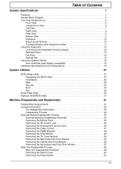
.... 4. Disassembly Process The disassembly process is divided into the following : 1. For example, if you want to remove the main board, you must first remove the keyboard, then disassemble the inside assembly frame in that you do the following stages: • External module disassembly •...)(NYLOK) 7 86.D01V7.001 M2.5*5-I (BNI)(NYLOK) 4 86.A03V7.003 M2.5*8-I BNI NYLOK 4 86.T48V7.001 42 Chapter 3 Remove the battery pack. General Information Pre-disassembly Instructions Before proceeding with the disassembly procedure, make sure that order. Unplug the AC adapter and all...
.... 4. Disassembly Process The disassembly process is divided into the following : 1. For example, if you want to remove the main board, you must first remove the keyboard, then disassemble the inside assembly frame in that you do the following stages: • External module disassembly •...)(NYLOK) 7 86.D01V7.001 M2.5*5-I (BNI)(NYLOK) 4 86.A03V7.003 M2.5*8-I BNI NYLOK 4 86.T48V7.001 42 Chapter 3 Remove the battery pack. General Information Pre-disassembly Instructions Before proceeding with the disassembly procedure, make sure that order. Unplug the AC adapter and all...

Aspire 6530/6530G Quick Guide
Page 53
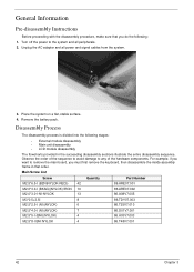
... main board, you on the entire disassembly sequence and instructs you must first remove the keyboard, then disassemble the inside assembly frame in that need to be removed during servicing. Turn off system and peripherals power Disconnect power and signal cables from system Rem ove Battery Rem ove SD Dummy Rem ove NewCard...
... main board, you on the entire disassembly sequence and instructs you must first remove the keyboard, then disassemble the inside assembly frame in that need to be removed during servicing. Turn off system and peripherals power Disconnect power and signal cables from system Rem ove Battery Rem ove SD Dummy Rem ove NewCard...
Aspire 6530/6530G Quick Guide
Page 69
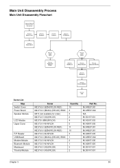
Main Unit Disassembly Process Main Unit Disassembly Flowchart Remove External Modules before proceeding Rem ove Switch Cover Rem ove Keyboard Rem ove Antenna Rem ove LCD Module Rem ove Power Board Rem ove Upper Cover Rem ove Fingerprint Reader Rem ove Lower Cover Rem ove ...
Main Unit Disassembly Process Main Unit Disassembly Flowchart Remove External Modules before proceeding Rem ove Switch Cover Rem ove Keyboard Rem ove Antenna Rem ove LCD Module Rem ove Power Board Rem ove Upper Cover Rem ove Fingerprint Reader Rem ove Lower Cover Rem ove ...
Aspire 6530/6530G Quick Guide
Page 70
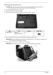
...page 44. 2. Step Switch Cover Size M2.5*6.5-I (BZN(NYLOK-RED) Quantity 10 Screw Type 4. See "Removing the Battery Pack" on a clean dry surface. 3. IMPORTANT:The LCD module does not fully extend. FFC... the LCD module to the outer casing. IMPORTANT:Do not remove at this point. It is recommended that only fingers are still attached on the bottom of the ...computer. Removing the Switch Cover CAUTION: Using tools to remove the Switch Cover may cause damage to expose the Switch Cover. Locate and remove the ten securing screws on the underside. ...
...page 44. 2. Step Switch Cover Size M2.5*6.5-I (BZN(NYLOK-RED) Quantity 10 Screw Type 4. See "Removing the Battery Pack" on a clean dry surface. 3. IMPORTANT:The LCD module does not fully extend. FFC... the LCD module to the outer casing. IMPORTANT:Do not remove at this point. It is recommended that only fingers are still attached on the bottom of the ...computer. Removing the Switch Cover CAUTION: Using tools to remove the Switch Cover may cause damage to expose the Switch Cover. Locate and remove the ten securing screws on the underside. ...

Aspire 6530/6530G Quick Guide
Page 73
See "Removing the Switch Cover" on page 60. 2. Unlock the connector and pull the FFC to expose the FFC. 3. Remove the keyboard from the chassis. Chapter 3 63 Removing the Keyboard 1. Lift and turn the keyboard over (as shown) to remove. 4. Remove the Switch Cover.
See "Removing the Switch Cover" on page 60. 2. Unlock the connector and pull the FFC to expose the FFC. 3. Remove the keyboard from the chassis. Chapter 3 63 Removing the Keyboard 1. Lift and turn the keyboard over (as shown) to remove. 4. Remove the Switch Cover.

Aspire 6530/6530G Quick Guide
Page 74
Remove the two securing screws (blue in the following image) the Speaker Module. Removing the Speaker Module 1. Screw Type 64 Chapter 3 Remove the three securing screws (red in the following image) from the Subwoofer Module. 3. Remove the Keyboard. Step Subwoofer Module (red callout) Speaker Module (blue callout) Size M3*3 3 (not available for order) M2.5*4.0-I (NI)(NYLOK) 2 Quantity 4. See "Removing the Keyboard" on page 63. 2. Disconnect the speaker cable as shown.
Remove the two securing screws (blue in the following image) the Speaker Module. Removing the Speaker Module 1. Screw Type 64 Chapter 3 Remove the three securing screws (red in the following image) from the Subwoofer Module. 3. Remove the Keyboard. Step Subwoofer Module (red callout) Speaker Module (blue callout) Size M3*3 3 (not available for order) M2.5*4.0-I (NI)(NYLOK) 2 Quantity 4. See "Removing the Keyboard" on page 63. 2. Disconnect the speaker cable as shown.


