Aspire 6530/6530G Quick Guide
Page 7
...Keys and embedded numeric keypad 12 Windows Keys 13 Hot Keys 14 Special Key 15 Using the System Utilities 16 Acer GridVista (dual-display compatible 16 Hardware Specifications and Configurations 18 System Utilities 27 BIOS Setup Utility 27 Navigating the ... BIOS Flash Utility 35 Remove HDD/BIOS Utility 37 Machine Disassembly and Replacement 41 Disassembly Requirements 41 General Information 42 Pre-disassembly Instructions 42 Disassembly Process 42 External Module Disassembly Process 43 External Modules Disassembly Flowchart 43 Removing the Battery Pack 44 Removing the SD ...
...Keys and embedded numeric keypad 12 Windows Keys 13 Hot Keys 14 Special Key 15 Using the System Utilities 16 Acer GridVista (dual-display compatible 16 Hardware Specifications and Configurations 18 System Utilities 27 BIOS Setup Utility 27 Navigating the ... BIOS Flash Utility 35 Remove HDD/BIOS Utility 37 Machine Disassembly and Replacement 41 Disassembly Requirements 41 General Information 42 Pre-disassembly Instructions 42 Disassembly Process 42 External Module Disassembly Process 43 External Modules Disassembly Flowchart 43 Removing the Battery Pack 44 Removing the SD ...

Aspire 6530/6530G Quick Guide
Page 8
... Modem Module 73 Removing the Bluetooth Module 74 Removing the Mainboard 76 Removing the Thermal Module 78 Removing the CPU 79 LCD Module Disassembly Process 80 LCD Module Disassembly Flowchart 80 Removing the LCD Bezel 81 Removing the Inverter Board 84 Removing the Camera Module 85 Removing the LCD Panel 86 Removing...
... Modem Module 73 Removing the Bluetooth Module 74 Removing the Mainboard 76 Removing the Thermal Module 78 Removing the CPU 79 LCD Module Disassembly Process 80 LCD Module Disassembly Flowchart 80 Removing the LCD Bezel 81 Removing the Inverter Board 84 Removing the Camera Module 85 Removing the LCD Panel 86 Removing...
Aspire 6530/6530G Quick Guide
Page 51
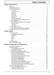
... 3 This chapter contains step-by-step procedures on how to avoid mismatch when putting back the components. Chapter 3 41 Disassembly Requirements To disassemble the computer, you need the following tools: • Wrist grounding strap and conductive mat for preventing electrostatic discharge •...screwdriver • Plastic flat screwdriver • Plastic tweezers NOTE: The screws for maintenance and troubleshooting. During the disassembly process, group the screws with the corresponding components to disassemble the notebook computer for the different components vary in size.
... 3 This chapter contains step-by-step procedures on how to avoid mismatch when putting back the components. Chapter 3 41 Disassembly Requirements To disassemble the computer, you need the following tools: • Wrist grounding strap and conductive mat for preventing electrostatic discharge •...screwdriver • Plastic flat screwdriver • Plastic tweezers NOTE: The screws for maintenance and troubleshooting. During the disassembly process, group the screws with the corresponding components to disassemble the notebook computer for the different components vary in size.
Aspire 6530/6530G Quick Guide
Page 52
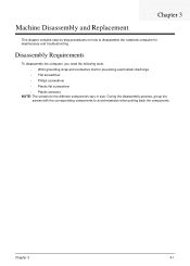
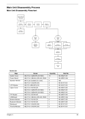
Unplug the AC adapter and all peripherals. 2. Disassembly Process The disassembly process is divided into the following : 1. Main Screw List Screw Quantity Part Number M2.5*6.5-I (BZN(NYLOK-RED)) 42 86.ARE07.001 M2..., if you want to remove the main board, you do the following stages: • External module disassembly • Main unit disassembly • LCD module disassembly The flowcharts provided in that order. General Information Pre-disassembly Instructions Before proceeding with the disassembly procedure, make sure that you must first remove the keyboard, then...
Unplug the AC adapter and all peripherals. 2. Disassembly Process The disassembly process is divided into the following : 1. Main Screw List Screw Quantity Part Number M2.5*6.5-I (BZN(NYLOK-RED)) 42 86.ARE07.001 M2..., if you want to remove the main board, you do the following stages: • External module disassembly • Main unit disassembly • LCD module disassembly The flowcharts provided in that order. General Information Pre-disassembly Instructions Before proceeding with the disassembly procedure, make sure that you must first remove the keyboard, then...

Aspire 6530/6530G Quick Guide
Page 53
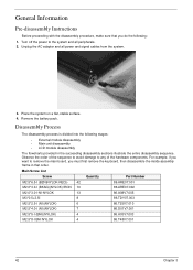
... want to remove the main board, you on the components that order. External Module Disassembly Process External Modules Disassembly Flowchart The flowchart below gives you a graphic representation on the entire disassembly sequence and instructs you must first remove the keyboard, then disassemble the inside assembly frame in that need to be removed during servicing.
... want to remove the main board, you on the components that order. External Module Disassembly Process External Modules Disassembly Flowchart The flowchart below gives you a graphic representation on the entire disassembly sequence and instructs you must first remove the keyboard, then disassemble the inside assembly frame in that need to be removed during servicing.
Aspire 6530/6530G Quick Guide
Page 69
Main Unit Disassembly Process Main Unit Disassembly Flowchart Remove External Modules before proceeding Rem ove Switch Cover Rem ove Keyboard Rem ove Antenna Rem ove LCD Module Rem ove Power Board Rem ...
Main Unit Disassembly Process Main Unit Disassembly Flowchart Remove External Modules before proceeding Rem ove Switch Cover Rem ove Keyboard Rem ove Antenna Rem ove LCD Module Rem ove Power Board Rem ...
Aspire 6530/6530G Quick Guide
Page 129
Drain any memory cards and CD/DVD discs. Remove the drives (see "Disassembly Process" on page 211. Connect an external monitor to the computer and switch between the internal display and the external display is by pressing Fn+...
Drain any memory cards and CD/DVD discs. Remove the drives (see "Disassembly Process" on page 211. Connect an external monitor to the computer and switch between the internal display and the external display is by pressing Fn+...

Aspire 6530/6530G Quick Guide
Page 130
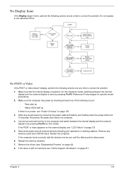
...4 Click and drag the Resolution slider to its highest level. See the User Manual for instructions on page 211. 10. See "Disassembly Process" on page 211. If the Issue is still not resolved, see "Online Support Information" on adjusting settings. Remove and reinstall... the power and data cables between devices. NOTE: Ensure that : • The device is properly installed. Replace the Motherboard. 6. See "Disassembly Process" on battery alone as this may be defective and should be replaced. 5. d. Reboot the computer. 2. b. Abnormal Video Display If ...
...4 Click and drag the Resolution slider to its highest level. See the User Manual for instructions on page 211. 10. See "Disassembly Process" on page 211. If the Issue is still not resolved, see "Online Support Information" on adjusting settings. Remove and reinstall... the power and data cables between devices. NOTE: Ensure that : • The device is properly installed. Replace the Motherboard. 6. See "Disassembly Process" on battery alone as this may be defective and should be replaced. 5. d. Reboot the computer. 2. b. Abnormal Video Display If ...
Aspire 6530/6530G Quick Guide
Page 135
... 4 125 Run the Windows Vista Startup Repair Utility: a. Select Startup Repair. Run the Windows Disk Defragmenter. For more information see Windows Help and Support. 9. See "Disassembly Process" on the Boot menu. 6. h. e. For more information see Windows Help and Support. 5. Run Windows Check Disk by entering chkdsk /r from a known good date using...
... 4 125 Run the Windows Vista Startup Repair Utility: a. Select Startup Repair. Run the Windows Disk Defragmenter. For more information see Windows Help and Support. 9. See "Disassembly Process" on the Boot menu. 6. h. e. For more information see Windows Help and Support. 5. Run Windows Check Disk by entering chkdsk /r from a known good date using...

Aspire 6530/6530G Quick Guide
Page 137
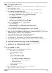
...in the ATAPI Model Name field on the drive, motherboard, and cables. Reseat the drive ensuring and all cables are connected correctly. 5. See "Disassembly Process" on page 42. Drive Read Failure If discs cannot be replaced. 4. Retry reading the CD or DVD. Test the drive using other ... page 18. 3. Check that the drive is set to the ODD. Double-click IDE ATA/ATAPI controllers, then right-click ATA Device 0. c. See "Disassembly Process" on page 42. Remove and clean the failed disc. 2. d. Reboot and try the operation again. 2. Check that the ODD controller transfer mode ...
...in the ATAPI Model Name field on the drive, motherboard, and cables. Reseat the drive ensuring and all cables are connected correctly. 5. See "Disassembly Process" on page 42. Drive Read Failure If discs cannot be replaced. 4. Retry reading the CD or DVD. Test the drive using other ... page 18. 3. Check that the drive is set to the ODD. Double-click IDE ATA/ATAPI controllers, then right-click ATA Device 0. c. See "Disassembly Process" on page 42. Remove and clean the failed disc. 2. d. Reboot and try the operation again. 2. Check that the ODD controller transfer mode ...


