
Acer Aspire 5951G Service Guide
Page 8
... Installation 3-52 LCD Module Removal 3-53 LCD Module Installation 3-53 Mainboard Removal 3-54 Mainboard Installation 3-57 PCH Heatsink Removal 3-58 PCH Heatsink Installation 3-59 RTC Battery Removal 3-60 RTC Battery Installation 3-61 Thermal Assembly Removal 3-62 Thermal Assembly Installation 3-63 CPU Removal 3-64 CPU Installation 3-65 Speaker Module Removal 3-66 Speaker Module Installation 3-67 Battery Removal 3-68 Battery Installation 3-68 DC-IN...
... Installation 3-52 LCD Module Removal 3-53 LCD Module Installation 3-53 Mainboard Removal 3-54 Mainboard Installation 3-57 PCH Heatsink Removal 3-58 PCH Heatsink Installation 3-59 RTC Battery Removal 3-60 RTC Battery Installation 3-61 Thermal Assembly Removal 3-62 Thermal Assembly Installation 3-63 CPU Removal 3-64 CPU Installation 3-65 Speaker Module Removal 3-66 Speaker Module Installation 3-67 Battery Removal 3-68 Battery Installation 3-68 DC-IN...

Acer Aspire 5951G Service Guide
Page 32
...connected. 1-22 Hardware Specifications and Configurations NOTE: To completely power off the system (equivalent to removing the battery), slide the battery reset switch to connect the internal battery. In this position, the computer will only function with screws) 3 Ventilation slots Enable the... computer to stay cool, even after prolonged use. 4 Battery release latch Slide to the disconnect battery position. Hard disk bay- NOTE: The computer battery is embedded and not removable. Base View No Icon Item 1 Sub woofer Description Emits low frequency sound...
...connected. 1-22 Hardware Specifications and Configurations NOTE: To completely power off the system (equivalent to removing the battery), slide the battery reset switch to connect the internal battery. In this position, the computer will only function with screws) 3 Ventilation slots Enable the... computer to stay cool, even after prolonged use. 4 Battery release latch Slide to the disconnect battery position. Hard disk bay- NOTE: The computer battery is embedded and not removable. Base View No Icon Item 1 Sub woofer Description Emits low frequency sound...

Acer Aspire 5951G Service Guide
Page 99
PCH Heatsink Removal 3-58 PCH Heatsink Installation 3-59 RTC Battery Removal 3-60 RTC Battery Installation 3-61 Thermal Assembly Removal 3-62 Thermal Assembly Installation 3-63 CPU Removal 3-64 CPU Installation 3-65 Speaker Module Removal 3-66 Speaker Module Installation 3-67 Battery Removal 3-68 Battery Installation 3-68 DC-IN Cable Removal 3-69 DC-IN Cable Installation 3-70 3-3
PCH Heatsink Removal 3-58 PCH Heatsink Installation 3-59 RTC Battery Removal 3-60 RTC Battery Installation 3-61 Thermal Assembly Removal 3-62 Thermal Assembly Installation 3-63 CPU Removal 3-64 CPU Installation 3-65 Speaker Module Removal 3-66 Speaker Module Installation 3-67 Battery Removal 3-68 Battery Installation 3-68 DC-IN Cable Removal 3-69 DC-IN Cable Installation 3-70 3-3

Acer Aspire 5951G Service Guide
Page 103
... and from the system. (Figure 3-2) 2. AC Adapter 3. Place system on logic door to any maintenance procedures: 1. Battery Disconnect Switch Machine Maintenance Procedures 3-7 Getting Started 0 The flowchart (Figure 3-1) identifies sections illustrating the entire removal and install sequence. Remove external power (A) from system. A Figure 3-2. Perform the following prior to performing any of the sequence to...
... and from the system. (Figure 3-2) 2. AC Adapter 3. Place system on logic door to any maintenance procedures: 1. Battery Disconnect Switch Machine Maintenance Procedures 3-7 Getting Started 0 The flowchart (Figure 3-1) identifies sections illustrating the entire removal and install sequence. Remove external power (A) from system. A Figure 3-2. Perform the following prior to performing any of the sequence to...

Acer Aspire 5951G Service Guide
Page 151
Figure 3-73. Disconnect battery cable (G) from lower cover slots (F), lift mainboard as shown in Figure 3-72. CAUTION: After mainboard removal, use caution not to show battery cable and mainboard connector as shown in Figure 3-73. F E Figure 3-72. Clearing Mainboard Ports ! Mainboard Overview (Bottom) with Battery Cable 5. Turn mainboard to damage touchpad connector. 4. To free mainboard ports (E) from mainboard connector (g). (Figure 3-74) Machine Maintenance Procedures 3-55 3.
Figure 3-73. Disconnect battery cable (G) from lower cover slots (F), lift mainboard as shown in Figure 3-72. CAUTION: After mainboard removal, use caution not to show battery cable and mainboard connector as shown in Figure 3-73. F E Figure 3-72. Clearing Mainboard Ports ! Mainboard Overview (Bottom) with Battery Cable 5. Turn mainboard to damage touchpad connector. 4. To free mainboard ports (E) from mainboard connector (g). (Figure 3-74) Machine Maintenance Procedures 3-55 3.

Acer Aspire 5951G Service Guide
Page 152
Disconnecting Battery Cable 6. Remove mainboard. 3-56 Machine Maintenance Procedures G g Figure 3-74.
Disconnecting Battery Cable 6. Remove mainboard. 3-56 Machine Maintenance Procedures G g Figure 3-74.

Acer Aspire 5951G Service Guide
Page 156
Disconnect battery cable (B) from mainboard adhesive. 3-60 Machine Maintenance Procedures Locate RTC battery (A) on mainboard. (Figure 3-77) A Figure 3-77. Remove battery from mainboard connector (b). (Figure 3-78) B b Figure 3-78. RTC Battery Removal. + IMPORTANT: Follow local regulations for battery disposal. 3. RTC Battery Removal 0 Prerequisite: Mainboard Removal 1. Mainboard Overview (Bottom) with RTC Battery 2.
Disconnect battery cable (B) from mainboard adhesive. 3-60 Machine Maintenance Procedures Locate RTC battery (A) on mainboard. (Figure 3-77) A Figure 3-77. Remove battery from mainboard connector (b). (Figure 3-78) B b Figure 3-78. RTC Battery Removal. + IMPORTANT: Follow local regulations for battery disposal. 3. RTC Battery Removal 0 Prerequisite: Mainboard Removal 1. Mainboard Overview (Bottom) with RTC Battery 2.

Acer Aspire 5951G Service Guide
Page 164
Install battery cable (B) through lower cover slot (C). 3. Battery Installation 0 1. Install speaker module. 3-68 Machine Maintenance Procedures Install battery (A) on lower cover. (Figure 3-88) A B C Figure 3-88. Make sure battery cable (B) is free from lower cover slot (C). 3. Remove battery. Battery Removal 0 Prerequisite: Speaker Module Removal 1. Locate battery (A) on lower cover. (Figure 3-88) 2. Lower Cover Overview with Battery 2.
Install battery cable (B) through lower cover slot (C). 3. Battery Installation 0 1. Install speaker module. 3-68 Machine Maintenance Procedures Install battery (A) on lower cover. (Figure 3-88) A B C Figure 3-88. Make sure battery cable (B) is free from lower cover slot (C). 3. Remove battery. Battery Removal 0 Prerequisite: Speaker Module Removal 1. Locate battery (A) on lower cover. (Figure 3-88) 2. Lower Cover Overview with Battery 2.

Acer Aspire 5951G Service Guide
Page 170
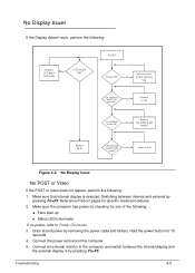
...powers off at intervals, perform the following : Start Check AC/Battery OK Swap M/B NG Swap AC/Battery try Figure 4-1. Remove all surge protectors between the computer and the outlet. 3. Remove any recently installed software. 7. Remove all external and non-essential hardware connected to the failure point....Unit Failure) and fan airways are not necessary to boot the computer to the computer that are free of obstructions. 5. Remove all extension cables between the computer and the electrical outlet. Plug the computer directly into a known serviceable electrical outlet. 4....
...powers off at intervals, perform the following : Start Check AC/Battery OK Swap M/B NG Swap AC/Battery try Figure 4-1. Remove all surge protectors between the computer and the outlet. 3. Remove any recently installed software. 7. Remove all external and non-essential hardware connected to the failure point....Unit Failure) and fan airways are not necessary to boot the computer to the computer that are free of obstructions. 5. Remove all extension cables between the computer and the electrical outlet. Plug the computer directly into a known serviceable electrical outlet. 4....
Acer Aspire 5951G Service Guide
Page 171
goto no power, refer to the computer and switch between internal and external by removing the power cable and battery. Reference Product pages for 10 seconds. 4. Hold the power button for specific model procedures. 2. DDR RAM module Replace M/B CPU thermal module well No screw? Drain ...
goto no power, refer to the computer and switch between internal and external by removing the power cable and battery. Reference Product pages for 10 seconds. 4. Hold the power button for specific model procedures. 2. DDR RAM module Replace M/B CPU thermal module well No screw? Drain ...
Acer Aspire 5951G Service Guide
Page 172
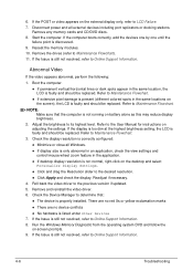
...-screen prompts. 9. Boot the computer. If permanent vertical/horizontal lines or dark spots appear in the same locations on battery alone as this may reduce display brightness. 2. Run the Windows Memory Diagnostic from the operating system DVD and follow the on the external... display only, refer to Online Support Information. 4-6 Troubleshooting 6. Remove any memory cards and CD/DVD discs. 8. If the computer boots correctly, add the devices one by one until the failure point is ...
...-screen prompts. 9. Boot the computer. If permanent vertical/horizontal lines or dark spots appear in the same locations on battery alone as this may reduce display brightness. 2. Run the Windows Memory Diagnostic from the operating system DVD and follow the on the external... display only, refer to Online Support Information. 4-6 Troubleshooting 6. Remove any memory cards and CD/DVD discs. 8. If the computer boots correctly, add the devices one by one until the failure point is ...

Acer Aspire 5951G Service Guide
Page 182
... that the power supply being used at a time. Remove power from the computer. 2. If any problems are supported by the computer. If the problem remains, replace the following devices: Non-Acer devices Printer, mouse, and other external devices Battery pack Hard disk drive ...
... that the power supply being used at a time. Remove power from the computer. 2. If any problems are supported by the computer. If the problem remains, replace the following devices: Non-Acer devices Printer, mouse, and other external devices Battery pack Hard disk drive ...

Acer Aspire 5951G Service Guide
Page 199
... of USB HDD. Update the latest BIOS version for this machine by the regular BIOS flashing process. 2. When CRISIS is saved in the same directory. 3. Remove battery and AC adaptor. 5.
... of USB HDD. Update the latest BIOS version for this machine by the regular BIOS flashing process. 2. When CRISIS is saved in the same directory. 3. Remove battery and AC adaptor. 5.


