Service Guide
Page 7
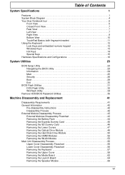
Table of Contents System Specifications 1 Features 1 System Block Diagram 4 Your Acer Notebook tour 5 Front View 5 Closed Front View 7 Rear View 7 Left View 7 Right View 9 Bottom View 10 TouchPad Basics (with ...Flash Utility 32 WinFlash Utility 34 Remove HDD/BIOS Password Utilities 35 Machine Disassembly and Replacement 41 Disassembly Requirements 41 General Information 42 Pre-disassembly Instructions 42 Disassembly Process 42 External Module Disassembly Process 43 External Modules Disassembly Flowchart 43 Removing the Battery Pack 44 Removing the Express Dummy Card 45...
Table of Contents System Specifications 1 Features 1 System Block Diagram 4 Your Acer Notebook tour 5 Front View 5 Closed Front View 7 Rear View 7 Left View 7 Right View 9 Bottom View 10 TouchPad Basics (with ...Flash Utility 32 WinFlash Utility 34 Remove HDD/BIOS Password Utilities 35 Machine Disassembly and Replacement 41 Disassembly Requirements 41 General Information 42 Pre-disassembly Instructions 42 Disassembly Process 42 External Module Disassembly Process 43 External Modules Disassembly Flowchart 43 Removing the Battery Pack 44 Removing the Express Dummy Card 45...

Service Guide
Page 53
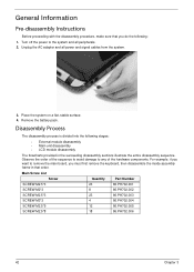
...of a regular metal screwdriver, however, a plastic screwdriver is advised when disassembling parts near or around the motherboard and to avoid mismatch when putting back the components. Disassembly Requirements To disassemble the computer, you need the following tools: • Wrist grounding ... tweezers NOTE: The screws for maintenance and troubleshooting. Chapter 3 Machine Disassembly and Replacement IMPORTANT: The outside housing and color may vary from the mass produced model. During the disassembly process, group the screws with the corresponding components to prevent scratching of...
...of a regular metal screwdriver, however, a plastic screwdriver is advised when disassembling parts near or around the motherboard and to avoid mismatch when putting back the components. Disassembly Requirements To disassemble the computer, you need the following tools: • Wrist grounding ... tweezers NOTE: The screws for maintenance and troubleshooting. Chapter 3 Machine Disassembly and Replacement IMPORTANT: The outside housing and color may vary from the mass produced model. During the disassembly process, group the screws with the corresponding components to prevent scratching of...
Service Guide
Page 54
..., make sure that order. Place the system on a flat, stable surface. 4. Disassembly Process The disassembly process is divided into the following : 1. Observe the order of the hardware components. Main Screw List Screw Quantity Part Number ... inside assembly frame in that you do the following stages: • External module disassembly • Main unit disassembly • LCD module disassembly The flowcharts provided in the succeeding disassembly sections illustrate the entire disassembly sequence. Remove the battery pack. Turn off the power to any of the sequence to avoid...
..., make sure that order. Place the system on a flat, stable surface. 4. Disassembly Process The disassembly process is divided into the following : 1. Observe the order of the hardware components. Main Screw List Screw Quantity Part Number ... inside assembly frame in that you do the following stages: • External module disassembly • Main unit disassembly • LCD module disassembly The flowcharts provided in the succeeding disassembly sections illustrate the entire disassembly sequence. Remove the battery pack. Turn off the power to any of the sequence to avoid...

Service Guide
Page 55
... Tuner (optional) WLAN Module M2*3 M2*3 2 86.PH702.002 2 86.PH702.002 Chapter 3 43 External Modules Disassembly Flowchart The flowchart below gives you a graphic representation on the entire disassembly sequence and instructs you on the components that order. Turn off system and peripherals power Disconnect power and signal cables...from the mass produced model. Screw List Step Screw Quantity Part No. For example, if you must first remove the keyboard, then disassemble the inside assembly frame in that need to remove the main board, you want to be present. External Module...
... Tuner (optional) WLAN Module M2*3 M2*3 2 86.PH702.002 2 86.PH702.002 Chapter 3 43 External Modules Disassembly Flowchart The flowchart below gives you a graphic representation on the entire disassembly sequence and instructs you on the components that order. Turn off system and peripherals power Disconnect power and signal cables...from the mass produced model. Screw List Step Screw Quantity Part No. For example, if you must first remove the keyboard, then disassemble the inside assembly frame in that need to remove the main board, you want to be present. External Module...

Service Guide
Page 67
Main Unit Disassembly Process Upper Cover Disassembly Flowchart Remove External Modules before proceeding Rem ove Keyboard Rem ove Upper Cover Lower Cover (see page 54) Upper Cover Rem ove Media Board Rem ...
Main Unit Disassembly Process Upper Cover Disassembly Flowchart Remove External Modules before proceeding Rem ove Keyboard Rem ove Upper Cover Lower Cover (see page 54) Upper Cover Rem ove Media Board Rem ...

Service Guide
Page 68
Lower Cover Disassembly Flowchart Remove External Modules before proceeding Rem ove Keyboard Rem ove Upper Cover Rem ove LCD Module Rem ove Bluetooth Module Rem ove Card Reader ...
Lower Cover Disassembly Flowchart Remove External Modules before proceeding Rem ove Keyboard Rem ove Upper Cover Rem ove LCD Module Rem ove Bluetooth Module Rem ove Card Reader ...

Service Guide
Page 89
Pull the Antenna cables through the cover as shown. Removing the LCD Module IMPORTANT: The LCD Module cannot be replaced. 1. Chapter 3 77 Disconnect the USB Board cable as shown. Remove the adhesive tapes securing the Antenna cables in place. 3. See "Removing the Upper Cover" on page 59. 2. Ensure that the Antennas are completely free from the cover. 4. If any part of the LCD Module is faulty, such as the camera, antenna or LCD panel, the whole module must be disassembled outside of factory conditions.
Pull the Antenna cables through the cover as shown. Removing the LCD Module IMPORTANT: The LCD Module cannot be replaced. 1. Chapter 3 77 Disconnect the USB Board cable as shown. Remove the adhesive tapes securing the Antenna cables in place. 3. See "Removing the Upper Cover" on page 59. 2. Ensure that the Antennas are completely free from the cover. 4. If any part of the LCD Module is faulty, such as the camera, antenna or LCD panel, the whole module must be disassembled outside of factory conditions.

Service Guide
Page 94
If any part of the LCD Module is faulty, such as the camera, antenna or LCD panel, the whole module must be disassembled outside of the Lower Cover. IMPORTANT: The LCD Module cannot be replaced. 82 Chapter 3 Using both hands, lift the LCD Module clear of factory conditions. 17.
If any part of the LCD Module is faulty, such as the camera, antenna or LCD panel, the whole module must be disassembled outside of the Lower Cover. IMPORTANT: The LCD Module cannot be replaced. 82 Chapter 3 Using both hands, lift the LCD Module clear of factory conditions. 17.

Service Guide
Page 117
IMPORTANT: Ensure that the cables pass through the Hinge Wells as shown to the Lower Cover. Replacing the LCD Module IMPORTANT: The LCD Module cannot be replaced. 1. Replace the four screws to secure the LCD Module to avoid trapping when the Upper Cover is faulty, such as the camera, antenna or LCD panel, the whole module must be disassembled outside of the LCD Module is replaced. 2. Align the LCD hinges with the Lower Cover screw holes and replace the LCD Module. Chapter 3 105 If any part of factory conditions.
IMPORTANT: Ensure that the cables pass through the Hinge Wells as shown to the Lower Cover. Replacing the LCD Module IMPORTANT: The LCD Module cannot be replaced. 1. Replace the four screws to secure the LCD Module to avoid trapping when the Upper Cover is faulty, such as the camera, antenna or LCD panel, the whole module must be disassembled outside of the LCD Module is replaced. 2. Align the LCD hinges with the Lower Cover screw holes and replace the LCD Module. Chapter 3 105 If any part of factory conditions.
Service Guide
Page 145
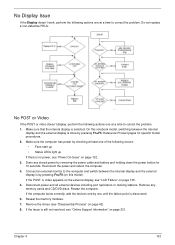
... video doesn't display, perform the following actions one at a time to correct the problem. If the POST or video appears on the external display, see "Disassembly Process" on page 135. 5. Remove the drives (see "LCD Failure" on page 42). 8.
... video doesn't display, perform the following actions one at a time to correct the problem. If the POST or video appears on the external display, see "Disassembly Process" on page 135. 5. Remove the drives (see "LCD Failure" on page 42). 8.
Service Guide
Page 146
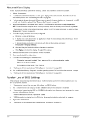
... present (different colored spots in the same locations on page 231. If extensive pixel damage is faulty and should be replaced. See "Disassembly Process" on page 42. 3. If desktop display resolution is not running on page 231. 134 Chapter 4 Readjust if necessary. 6. Check...LCD is experiencing intermittent loss of BIOS Settings If the computer is faulty and should be replaced. e. Replace the Motherboard. 6. See "Disassembly Process" on the desktop and select Personalize´ Display Settings. b. Click and drag the Resolution slider to its highest level. Random ...
... present (different colored spots in the same locations on page 231. If extensive pixel damage is faulty and should be replaced. See "Disassembly Process" on page 42. 3. If desktop display resolution is not running on page 231. 134 Chapter 4 Readjust if necessary. 6. Check...LCD is experiencing intermittent loss of BIOS Settings If the computer is faulty and should be replaced. e. Replace the Motherboard. 6. See "Disassembly Process" on the desktop and select Personalize´ Display Settings. b. Click and drag the Resolution slider to its highest level. Random ...
Service Guide
Page 151
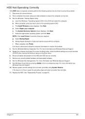
... Support. 10. Restart the computer and press F2 to locate and resolve issues with the computer. For more information see Windows Help and Support. 9. See "Disassembly Process" on the Boot menu. 6. Disconnect all cables and jumpers on the HDD and ODD are set as the first boot device on page 42...
... Support. 10. Restart the computer and press F2 to locate and resolve issues with the computer. For more information see Windows Help and Support. 9. See "Disassembly Process" on the Boot menu. 6. Disconnect all cables and jumpers on the HDD and ODD are set as the first boot device on page 42...
Service Guide
Page 154
... page 42. Restart the computer and press F2 to correct the problem. 1. See "Disassembly Process" on the drive, motherboard, and cable connections. Check for the other discs. c. See "Disassembly Process" on the drive, motherboard, and cables. Double-click IDE ATA/ATAPI controllers, ...Try an alternate cable, if available. Click Properties and select the Advanced Settings tab. See "Disassembly Process" on page 42. Test the drive using other ATA Devices shown if applicable. See "Disassembly Process" on page 42. e. a. Ensure that the drive is identical to a music CD...
... page 42. Restart the computer and press F2 to correct the problem. 1. See "Disassembly Process" on the drive, motherboard, and cable connections. Check for the other discs. c. See "Disassembly Process" on the drive, motherboard, and cables. Double-click IDE ATA/ATAPI controllers, ...Try an alternate cable, if available. Click Properties and select the Advanced Settings tab. See "Disassembly Process" on page 42. Test the drive using other ATA Devices shown if applicable. See "Disassembly Process" on page 42. e. a. Ensure that the drive is identical to a music CD...
Service Guide
Page 245
... 6 CPU 96 Replacing 97 Index D DIMM Modules Removing 52 Display 4 display hotkeys 14 E EasyTouch Failure 144 Euro 15 Express Dummy Card Removing 45 External Module Disassembly Flowchart 43 F Features 1 Finger Print Reader Removing 72 Replacing 108 Flash Utility 31 FRU (Field Replaceable Unit) List 167 H Hard Disk Drive Module Removing 50...
... 6 CPU 96 Replacing 97 Index D DIMM Modules Removing 52 Display 4 display hotkeys 14 E EasyTouch Failure 144 Euro 15 Express Dummy Card Removing 45 External Module Disassembly Flowchart 43 F Features 1 Finger Print Reader Removing 72 Replacing 108 Flash Utility 31 FRU (Field Replaceable Unit) List 167 H Hard Disk Drive Module Removing 50...
Service Guide
Page 246
... LCD Module Removing 77 Left Hinge Well Removing 90 Replacing 101 Left Saddle Removing 83 Replacing 104 Lower Cover Disassembly Flowchart 56 Lower Covers Removing 47 M Main Module Reassembly Procedure 97 Main Unit Disassembly Flowchart 55 Mainboard Removing 91 Replacing 100 media access on indicator 6 Media Board Removing 62 Replacing 119 Memory...
... LCD Module Removing 77 Left Hinge Well Removing 90 Replacing 101 Left Saddle Removing 83 Replacing 104 Lower Cover Disassembly Flowchart 56 Lower Covers Removing 47 M Main Module Reassembly Procedure 97 Main Unit Disassembly Flowchart 55 Mainboard Removing 91 Replacing 100 media access on indicator 6 Media Board Removing 62 Replacing 119 Memory...

Service Guide
Page 247
... 133 ODD 140 Other Failures 145 Power On 132 Thermal Unit 144 TouchPad 136 WLAN 143 U Undetermined Problems 146 Upper Cover Removing 59 Upper Cover Disassembly Flowchart 55 USB Board Removing 85 Replacing 103 utility BIOS 23-31 V VGA Card Removing 93 VGA/MXM Card Replacing 99 Volume Control Board Removing...
... 133 ODD 140 Other Failures 145 Power On 132 Thermal Unit 144 TouchPad 136 WLAN 143 U Undetermined Problems 146 Upper Cover Removing 59 Upper Cover Disassembly Flowchart 55 USB Board Removing 85 Replacing 103 utility BIOS 23-31 V VGA Card Removing 93 VGA/MXM Card Replacing 99 Volume Control Board Removing...


