Aspire 5755, 5755G Service Guide
Page 3
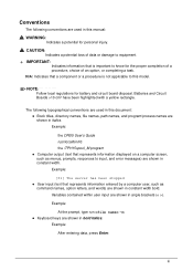
... is important to know for the proper completion of a procedure, choice of an option, or completing a task. Example: At the prompt, type run -m Keyboard keys are shown in constant width. CAUTION: Indicates a potential loss of data or damage to equipment. + IMPORTANT: Indicates information that represents information entered by a computer...
... is important to know for the proper completion of a procedure, choice of an option, or completing a task. Example: At the prompt, type run -m Keyboard keys are shown in constant width. CAUTION: Indicates a potential loss of data or damage to equipment. + IMPORTANT: Indicates information that represents information entered by a computer...

Aspire 5755, 5755G Service Guide
Page 5
...1-9 Software 1-9 Notebook Tour 1-11 Top View 1-11 Closed Front View 1-13 Left View 1-14 Right View 1-15 Base View 1-16 Touchpad Basics 1-17 Using the Keyboard 1-18 Windows Keys 1-19 Hotkeys 1-20 System Block Diagram 1-22 Specification Tables 1-23 Computer specifications 1-23 System Board Major Chips 1-24 Processor 1-24 Processor Specifications... 1-24 CPU Fan True Value Table (Tj=100 1-25 System Memory 1-25 Memory Combinations 1-26 Video Interface 1-26 BIOS 1-27 LAN Interface 1-27 Keyboard 1-27 Hard Disk Drive (AVL components 1-28 Super-Multi Drive 1-30 v
...1-9 Software 1-9 Notebook Tour 1-11 Top View 1-11 Closed Front View 1-13 Left View 1-14 Right View 1-15 Base View 1-16 Touchpad Basics 1-17 Using the Keyboard 1-18 Windows Keys 1-19 Hotkeys 1-20 System Block Diagram 1-22 Specification Tables 1-23 Computer specifications 1-23 System Board Major Chips 1-24 Processor 1-24 Processor Specifications... 1-24 CPU Fan True Value Table (Tj=100 1-25 System Memory 1-25 Memory Combinations 1-26 Video Interface 1-26 BIOS 1-27 LAN Interface 1-27 Keyboard 1-27 Hard Disk Drive (AVL components 1-28 Super-Multi Drive 1-30 v

Aspire 5755, 5755G Service Guide
Page 7
... 3-33 USB Module Removal 3-34 USB Module Installation 3-35 Bluetooth Module Removal 3-36 Bluetooth Module Installation 3-37 Power Board Removal 3-38 Power Board Installation 3-39 Keyboard Assembly Removal 3-40 Keyboard Assembly Installation 3-41 Speaker Module Removal 3-42 Speaker Module Installation 3-43 vii
... 3-33 USB Module Removal 3-34 USB Module Installation 3-35 Bluetooth Module Removal 3-36 Bluetooth Module Installation 3-37 Power Board Removal 3-38 Power Board Installation 3-39 Keyboard Assembly Removal 3-40 Keyboard Assembly Installation 3-41 Speaker Module Removal 3-42 Speaker Module Installation 3-43 vii

Aspire 5755, 5755G Service Guide
Page 8
... 3G Antenna Installation 3-63 Microphone Set Removal 3-64 Microphone Set Installation 3-64 CHAPTER 4 Troubleshooting Introduction 4-3 General Information 4-3 Power On Issues 4-4 No Display Issues 4-5 LCD Failure 4-7 Keyboard Failure 4-8 Touchpad Failure 4-9 Internal Speaker Failure 4-10 Microphone Failure 4-12 USB Failure 4-13 Wireless Function Failure 4-14 Bluetooth Failure 4-15 Card Reader Failure 4-16 Thermal...
... 3G Antenna Installation 3-63 Microphone Set Removal 3-64 Microphone Set Installation 3-64 CHAPTER 4 Troubleshooting Introduction 4-3 General Information 4-3 Power On Issues 4-4 No Display Issues 4-5 LCD Failure 4-7 Keyboard Failure 4-8 Touchpad Failure 4-9 Internal Speaker Failure 4-10 Microphone Failure 4-12 USB Failure 4-13 Wireless Function Failure 4-14 Bluetooth Failure 4-15 Card Reader Failure 4-16 Thermal...

Aspire 5755, 5755G Service Guide
Page 12
... Notebook Tour 1-11 Top View 1-11 Closed Front View 1-13 Left View 1-14 Right View 1-15 Base View 1-16 Touchpad Basics 1-17 Using the Keyboard 1-18 Windows Keys 1-19 Hotkeys 1-20 System Block Diagram 1-22 Specification Tables 1-23 Computer specifications 1-23 System Board Major Chips 1-24 Processor 1-24 Processor... Fan True Value Table (Tj=100 1-25 System Memory 1-25 Memory Combinations 1-26 Video Interface 1-26 BIOS 1-27 LAN Interface 1-27 Keyboard 1-27 Hard Disk Drive (AVL components 1-28 Super-Multi Drive 1-30 LED 15.6 1-32 Display Supported Resolution (LCD 1-32 1-2
... Notebook Tour 1-11 Top View 1-11 Closed Front View 1-13 Left View 1-14 Right View 1-15 Base View 1-16 Touchpad Basics 1-17 Using the Keyboard 1-18 Windows Keys 1-19 Hotkeys 1-20 System Block Diagram 1-22 Specification Tables 1-23 Computer specifications 1-23 System Board Major Chips 1-24 Processor 1-24 Processor... Fan True Value Table (Tj=100 1-25 System Memory 1-25 Memory Combinations 1-26 Video Interface 1-26 BIOS 1-27 LAN Interface 1-27 Keyboard 1-27 Hard Disk Drive (AVL components 1-28 Super-Multi Drive 1-30 LED 15.6 1-32 Display Supported Resolution (LCD 1-32 1-2

Aspire 5755, 5755G Service Guide
Page 18
...support External display (VGA) port Headphone/speaker jack, supporting 3.5 mm headset with built-in microphone for Acer smart handhelds Microphone-in jack Ethernet (RJ-45) port DC-in jack for AC adapter ...Special Keys and Controls 0 Keyboard 103-/104-/107-key Acer FineTip keyboard with independent standard numeric keypad, international language support Touchpad Multi-gesture touchpad, supporting two-finger scroll,...
...support External display (VGA) port Headphone/speaker jack, supporting 3.5 mm headset with built-in microphone for Acer smart handhelds Microphone-in jack Ethernet (RJ-45) port DC-in jack for AC adapter ...Special Keys and Controls 0 Keyboard 103-/104-/107-key Acer FineTip keyboard with independent standard numeric keypad, international language support Touchpad Multi-gesture touchpad, supporting two-finger scroll,...

Aspire 5755, 5755G Service Guide
Page 22
... active. Indicates when the hard disk drive is charging. Fully charged: The light shows blue when in AC mode. Indicates the computer's power status. 4 Keyboard For entering data into your computer. 5 Touchpad Touch-sensitive pointing device which functions like the left and right buttons function like a computer mouse. 6 Power indicator...
... active. Indicates when the hard disk drive is charging. Fully charged: The light shows blue when in AC mode. Indicates the computer's power status. 4 Keyboard For entering data into your computer. 5 Touchpad Touch-sensitive pointing device which functions like the left and right buttons function like a computer mouse. 6 Power indicator...

Aspire 5755, 5755G Service Guide
Page 28
... access Num Lock on Number keys on and off by using Home, PgUp, PgDn, End, Ins, Del and arrow keys. Keyboard Lock Keys The keyboard has three lock keys which can be toggled on keypad Hold while using cursor-control keys. 1-18 Hardware Specifications and Configurations The ...keys function as a calculator (complete with some applications. Scroll Lock does not work with the arithmetic operators +, -, *, and /). The keyboard also contains a numeric keypad which can be to connect an external keypad. Num Lock off . (Table 1-7) Table 1-7. Using the...
... access Num Lock on Number keys on and off by using Home, PgUp, PgDn, End, Ins, Del and arrow keys. Keyboard Lock Keys The keyboard has three lock keys which can be toggled on keypad Hold while using cursor-control keys. 1-18 Hardware Specifications and Configurations The ...keys function as a calculator (complete with some applications. Scroll Lock does not work with the arithmetic operators +, -, *, and /). The keyboard also contains a numeric keypad which can be to connect an external keypad. Num Lock off . (Table 1-7) Table 1-7. Using the...
Aspire 5755, 5755G Service Guide
Page 29
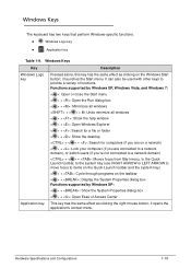
... the system tray) < > + : Cycle through programs on the Windows Start button; it opens the application's context menu. it launches the Start menu. Windows Keys 0 The keyboard has two keys that perform Windows-specific functions. Windows Logo key Application key Table 1-9. Windows Keys Key Description Windows Logo key...
... the system tray) < > + : Cycle through programs on the Windows Start button; it opens the application's context menu. it launches the Start menu. Windows Keys 0 The keyboard has two keys that perform Windows-specific functions. Windows Logo key Application key Table 1-9. Windows Keys Key Description Windows Logo key...
Aspire 5755, 5755G Service Guide
Page 30
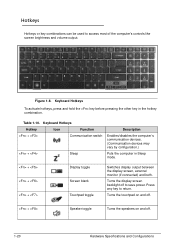
...on and off to save power. Table 1-10. Turns the display screen backlight off . 1-20 Hardware Specifications and Configurations Keyboard Hotkeys Hotkey Icon Function + Communication switch + Sleep Description Enables/disables the computer's communication devices. (Communication devices may vary... by configuration.) Puts the computer in the hotkey combination. Keyboard Hotkeys To activate hotkeys, press and hold the key before pressing the other key in Sleep mode. + + + Display...
...on and off to save power. Table 1-10. Turns the display screen backlight off . 1-20 Hardware Specifications and Configurations Keyboard Hotkeys Hotkey Icon Function + Communication switch + Sleep Description Enables/disables the computer's communication devices. (Communication devices may vary... by configuration.) Puts the computer in the hotkey combination. Keyboard Hotkeys To activate hotkeys, press and hold the key before pressing the other key in Sleep mode. + + + Display...
Aspire 5755, 5755G Service Guide
Page 31
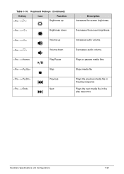
Plays or pauses media files Stops media file Plays the previous media file in the play sequence Plays the next media file in the play sequence Hardware Specifications and Configurations 1-21 Increases audio volume. Decreases audio volume. Keyboard Hotkeys (Continued) Hotkey + Icon Function Brightness up + Brightness down + Volume up + Volume down + Play/Pause + Stop + Previous + Next Description Increases the screen brightness. Decreases the screen brightness. Table 1-10.
Plays or pauses media files Stops media file Plays the previous media file in the play sequence Plays the next media file in the play sequence Hardware Specifications and Configurations 1-21 Increases audio volume. Decreases audio volume. Keyboard Hotkeys (Continued) Hotkey + Icon Function Brightness up + Brightness down + Volume up + Volume down + Play/Pause + Stop + Previous + Next Description Increases the screen brightness. Decreases the screen brightness. Table 1-10.

Aspire 5755, 5755G Service Guide
Page 37
...at the left side Supports 10/100/1000 Keyboard Item Type Total number of keypads Windows logo key Internal & external keyboard work simultaneously Features Specification New Acer AC7T flat keyboard 103-US/104-UK /107-JP keys Yes Plug USB keyboard to Acer BIOS specification. BIOS Item BIOS vendor BIOS ...Version BIOS ROM type BIOS ROM size Features Specification Insyde 1.11 SPI 4MB Insyde code base Flash ROM 4 MB Support Acer UI Support multi-boot ...
...at the left side Supports 10/100/1000 Keyboard Item Type Total number of keypads Windows logo key Internal & external keyboard work simultaneously Features Specification New Acer AC7T flat keyboard 103-US/104-UK /107-JP keys Yes Plug USB keyboard to Acer BIOS specification. BIOS Item BIOS vendor BIOS ...Version BIOS ROM type BIOS ROM size Features Specification Insyde 1.11 SPI 4MB Insyde code base Flash ROM 4 MB Support Acer UI Support multi-boot ...

Aspire 5755, 5755G Service Guide
Page 80
... 3-33 USB Module Removal 3-34 USB Module Installation 3-35 Bluetooth Module Removal 3-36 Bluetooth Module Installation 3-37 Power Board Removal 3-38 Power Board Installation 3-39 Keyboard Assembly Removal 3-40 Keyboard Assembly Installation 3-41 Speaker Module Removal 3-42 Speaker Module Installation 3-43 Mainboard Removal 3-44 3-2
... 3-33 USB Module Removal 3-34 USB Module Installation 3-35 Bluetooth Module Removal 3-36 Bluetooth Module Installation 3-37 Power Board Removal 3-38 Power Board Installation 3-39 Keyboard Assembly Removal 3-40 Keyboard Assembly Installation 3-41 Speaker Module Removal 3-42 Speaker Module Installation 3-43 Mainboard Removal 3-44 3-2

Aspire 5755, 5755G Service Guide
Page 105
Machine Maintenance Procedures 3-27 Palmrest Removal from lower cover. Remove palmrest from Lower Cover 5. Release touchpad FFC (C) from Touchpad Board 6. C D Figure 3-26. 4. Put palmrest (E) on keyboard (Figure 3-25). E Figure 3-25. Touchpad FFC Removal from touchpad module connector (D) (Figure 3-26).
Machine Maintenance Procedures 3-27 Palmrest Removal from lower cover. Remove palmrest from Lower Cover 5. Release touchpad FFC (C) from Touchpad Board 6. C D Figure 3-26. 4. Put palmrest (E) on keyboard (Figure 3-25). E Figure 3-25. Touchpad FFC Removal from touchpad module connector (D) (Figure 3-26).

Aspire 5755, 5755G Service Guide
Page 106
Put palmrest onto lower cover. (Figure 3-25) 4. Install HDD module. 7. Install base door. Palmrest Assembly 2. Install and secure six (6) screws (A) to touchpad module connector (D) (Figure 3-26). 3. ID Size A M2.45x8.0 Quantity 8 Screw Type B M2.5x5.0 2 3-28 Machine Maintenance Procedures Palmrest Assembly Installation 0 1. Connect touchpad FFC (C) to lower cover. (Figure 3-22) 6. E E Figure 3-27. Install and secure two (2) screws (B) to lower cover. (Figure 3-23) 5. Align palmrest assembly (E) with the keyboard as shown in Figure 3-27.
Put palmrest onto lower cover. (Figure 3-25) 4. Install HDD module. 7. Install base door. Palmrest Assembly 2. Install and secure six (6) screws (A) to touchpad module connector (D) (Figure 3-26). 3. ID Size A M2.45x8.0 Quantity 8 Screw Type B M2.5x5.0 2 3-28 Machine Maintenance Procedures Palmrest Assembly Installation 0 1. Connect touchpad FFC (C) to lower cover. (Figure 3-22) 6. E E Figure 3-27. Install and secure two (2) screws (B) to lower cover. (Figure 3-23) 5. Align palmrest assembly (E) with the keyboard as shown in Figure 3-27.

Aspire 5755, 5755G Service Guide
Page 109
Exposing Keyboard FPC and Power Board FFC 7. F H C E G Figure 3-32. Disconnect power board FFC (F) from lower cover. Remove upper cover from mainboard connector (H). 9. 6. Disconnect keyboard FPC (E) from mainboard connector (G). 8. Machine Maintenance Procedures 3-31 Move upper cover until keyboard FPC (E) and power board FFC (F) cables are visible (Figure 3-32).
Exposing Keyboard FPC and Power Board FFC 7. F H C E G Figure 3-32. Disconnect power board FFC (F) from lower cover. Remove upper cover from mainboard connector (H). 9. 6. Disconnect keyboard FPC (E) from mainboard connector (G). 8. Machine Maintenance Procedures 3-31 Move upper cover until keyboard FPC (E) and power board FFC (F) cables are visible (Figure 3-32).

Aspire 5755, 5755G Service Guide
Page 110
... Type A,C M2.45x8.0 11 3-32 Machine Maintenance Procedures Install and secure screw (C) to mainboard connector (G). (Figure 3-32) 3. Place computer facedown. 7. Make sure keyboard FPC (E) is visible. (Figure 3-32) 2. Connect keyboard FPC (E) to upper cover (Figure 3-30). 6. Connect power board FFC (F) to lower cover. Install palmrest assembly. Align upper cover to mainboard connector...
... Type A,C M2.45x8.0 11 3-32 Machine Maintenance Procedures Install and secure screw (C) to mainboard connector (G). (Figure 3-32) 3. Place computer facedown. 7. Make sure keyboard FPC (E) is visible. (Figure 3-32) 2. Connect keyboard FPC (E) to upper cover (Figure 3-30). 6. Connect power board FFC (F) to lower cover. Install palmrest assembly. Align upper cover to mainboard connector...

Aspire 5755, 5755G Service Guide
Page 118
Slide keyboard support plate toward top edge (D) of upper cover. 4. Machine Maintenance Procedures Keyboard Assembly Removal 0 Prerequisite: Upper Cover Removal 1. Remove keyboard support plate (E) from upper cover. (Figure 3-43) G 3-40 Figure 3-43. Upper Cover without Keyboard Support Plate. Peel back mylar as required. 2. Remove keyboard (G) from upper cover. 5. Keyboard Assembly Screws 3. Remove three (3) screws (A), two (2) screws (B), and five (5) screws (C) from keyboard. (Figure 3-42) A D A A C B F E Figure 3-42.
Slide keyboard support plate toward top edge (D) of upper cover. 4. Machine Maintenance Procedures Keyboard Assembly Removal 0 Prerequisite: Upper Cover Removal 1. Remove keyboard support plate (E) from upper cover. (Figure 3-43) G 3-40 Figure 3-43. Upper Cover without Keyboard Support Plate. Peel back mylar as required. 2. Remove keyboard (G) from upper cover. 5. Keyboard Assembly Screws 3. Remove three (3) screws (A), two (2) screws (B), and five (5) screws (C) from keyboard. (Figure 3-42) A D A A C B F E Figure 3-42.

Aspire 5755, 5755G Service Guide
Page 119
... secured under latch guide (H). (Figure 3-44) K J K J H Figure 3-44. ID Size A M2.0x2.5 Quantity 3 Screw Type B M1.6x2.0 Ni 2 C M1.6x3.0 5 Machine Maintenance Procedures 3-41 Keyboard Support Plate Guides 4. Install upper cover. Slide keyboard support plate toward bottom edge (F) of upper cover. Install and secure three (3) screws (A), two (2) screws (B), and five (5) screws (C) to...
... secured under latch guide (H). (Figure 3-44) K J K J H Figure 3-44. ID Size A M2.0x2.5 Quantity 3 Screw Type B M1.6x2.0 Ni 2 C M1.6x3.0 5 Machine Maintenance Procedures 3-41 Keyboard Support Plate Guides 4. Install upper cover. Slide keyboard support plate toward bottom edge (F) of upper cover. Install and secure three (3) screws (A), two (2) screws (B), and five (5) screws (C) to...

Aspire 5755, 5755G Service Guide
Page 144
Introduction 4-3 General Information 4-3 Power On Issues 4-4 No Display Issues 4-5 LCD Failure 4-7 Keyboard Failure 4-8 Touchpad Failure 4-9 Internal Speaker Failure 4-10 Microphone Failure 4-12 USB Failure 4-13 Wireless Function Failure 4-14 Bluetooth Failure 4-15 Card Reader Failure 4-16 Thermal Unit Failure 4-17 Other Functions Failure 4-18 CosmeticFailure 4-19 ODD Failure 4-20 Intermittent Problems 4-24 Undetermined Problems 4-24 Post Codes 4-25 4-2
Introduction 4-3 General Information 4-3 Power On Issues 4-4 No Display Issues 4-5 LCD Failure 4-7 Keyboard Failure 4-8 Touchpad Failure 4-9 Internal Speaker Failure 4-10 Microphone Failure 4-12 USB Failure 4-13 Wireless Function Failure 4-14 Bluetooth Failure 4-15 Card Reader Failure 4-16 Thermal Unit Failure 4-17 Other Functions Failure 4-18 CosmeticFailure 4-19 ODD Failure 4-20 Intermittent Problems 4-24 Undetermined Problems 4-24 Post Codes 4-25 4-2


