
Service Guide
Page 29
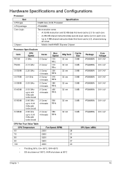
... 3 MB 3 MB Package rPGA988A Core Voltage 0.8-1.4V rPGA988A 0.8-1.4V rPGA988A 0.8-1.4V rPGA988A 0.8-1.4V rPGA988A 0.8-1.4V rPGA988A 0.8-1.4V rPGA988A 0.8-1.4V rPGA988A 0.8-1.4V CPU Fan True Value Table CPU Temperature Fan Speed (RPM) 60 2500 28 70 2900 31 80 3200 34 90 3600 37 100 4000 40 SPL Spec (dBA) • Throttling 50...
... 3 MB 3 MB Package rPGA988A Core Voltage 0.8-1.4V rPGA988A 0.8-1.4V rPGA988A 0.8-1.4V rPGA988A 0.8-1.4V rPGA988A 0.8-1.4V rPGA988A 0.8-1.4V rPGA988A 0.8-1.4V rPGA988A 0.8-1.4V CPU Fan True Value Table CPU Temperature Fan Speed (RPM) 60 2500 28 70 2900 31 80 3200 34 90 3600 37 100 4000 40 SPL Spec (dBA) • Throttling 50...
Service Guide
Page 99
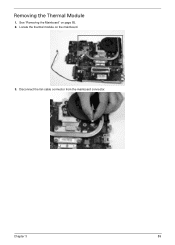
Disconnect the fan cable connector from the mainboard connector. Chapter 3 89 Locate the thermal module on page 85. 2. Removing the Thermal Module 1. See "Removing the Mainboard" on the mainboard. 3.
Disconnect the fan cable connector from the mainboard connector. Chapter 3 89 Locate the thermal module on page 85. 2. Removing the Thermal Module 1. See "Removing the Mainboard" on the mainboard. 3.
Service Guide
Page 170
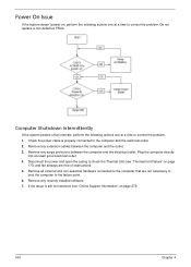
... system powers off at intervals, perform the following actions one at a time to check the Thermal Unit (see "Online Support Information" on page 173) and fan airways are not necessary to boot the computer to the computer and the electrical outlet. 2. If the Issue is properly connected to the failure point. 6.
... system powers off at intervals, perform the following actions one at a time to check the Thermal Unit (see "Online Support Information" on page 173) and fan airways are not necessary to boot the computer to the computer and the electrical outlet. 2. If the Issue is properly connected to the failure point. 6.
Service Guide
Page 171
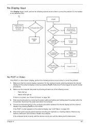
... reboot the computer. 4. Do not replace a non-defective FRU: No POST or Video If the POST or video doesn't display, perform the following occurs: • Fans start up • Status LEDs light up If there is no power, see "LCD Failure" on page 160. 3. Reference Product pages for 10 seconds. If...
... reboot the computer. 4. Do not replace a non-defective FRU: No POST or Video If the POST or video doesn't display, perform the following occurs: • Fans start up • Status LEDs light up If there is no power, see "LCD Failure" on page 160. 3. Reference Product pages for 10 seconds. If...
Service Guide
Page 210
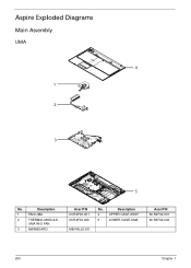
UMA W/O FAN 3 MAINBOARD Acer P/N 23.R4F02.001 60.R4F02.006 MB.R4L02.001 No. Description 1 FAN-UMA 2 THERMAL MODULE- Aspire Exploded Diagrams Main Assembly UMA 4 1 2 3 5 No. Description 4 UPPER CASE ASSY 5 LOWER CASE-UMA Acer P/N 60.R4F02.001 60.R4F02.002 200 Chapter 1
UMA W/O FAN 3 MAINBOARD Acer P/N 23.R4F02.001 60.R4F02.006 MB.R4L02.001 No. Description 1 FAN-UMA 2 THERMAL MODULE- Aspire Exploded Diagrams Main Assembly UMA 4 1 2 3 5 No. Description 4 UPPER CASE ASSY 5 LOWER CASE-UMA Acer P/N 60.R4F02.001 60.R4F02.002 200 Chapter 1
Service Guide
Page 238
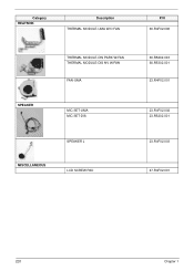
Category HEATSINK Description THERMAL MODULE-UMA W/O FAN P/N 60.R4F02.006 SPEAKER THERMAL MODULE-DIS PARK W/FAN THERMAL MODULE-DIS NV W/FAN FAN-UMA MIC SET-UMA MIC SET-DIS SPEAKER L MISCELLANEOUS LCD SCREW PAD 60.R5202.003 60.R5302.001 23.R4F02.001 23.R4F02.002 23.R5202.001 23.R4F02.003 47.R4F02.001 228 Chapter 1
Category HEATSINK Description THERMAL MODULE-UMA W/O FAN P/N 60.R4F02.006 SPEAKER THERMAL MODULE-DIS PARK W/FAN THERMAL MODULE-DIS NV W/FAN FAN-UMA MIC SET-UMA MIC SET-DIS SPEAKER L MISCELLANEOUS LCD SCREW PAD 60.R5202.003 60.R5302.001 23.R4F02.001 23.R4F02.002 23.R5202.001 23.R4F02.003 47.R4F02.001 228 Chapter 1


