Service Guide
Page 7
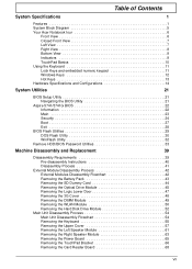
Table of Contents System Specifications 1 Features 1 System Block Diagram 5 Your Acer Notebook tour 6 Front View 6 Closed Front View 7 Left View 7 Right View 8...14 System Utilities 21 BIOS Setup Utility 21 Navigating the BIOS Utility 21 Aspire 5741/5741G BIOS 22 Information 22 Main 23 Security 24 Boot 27 Exit 28 BIOS Flash Utilities 29 DOS Flash Utility 30 WinFlash ... the 3G Cover 48 Removing the DIMM Module 49 Removing the WLAN Module 50 Removing the Hard Disk Drive Module 52 Main Unit Disassembly Process 54 Main Unit Disassembly Flowchart 54 Removing the Keyboard 55...
Table of Contents System Specifications 1 Features 1 System Block Diagram 5 Your Acer Notebook tour 6 Front View 6 Closed Front View 7 Left View 7 Right View 8...14 System Utilities 21 BIOS Setup Utility 21 Navigating the BIOS Utility 21 Aspire 5741/5741G BIOS 22 Information 22 Main 23 Security 24 Boot 27 Exit 28 BIOS Flash Utilities 29 DOS Flash Utility 30 WinFlash ... the 3G Cover 48 Removing the DIMM Module 49 Removing the WLAN Module 50 Removing the Hard Disk Drive Module 52 Main Unit Disassembly Process 54 Main Unit Disassembly Flowchart 54 Removing the Keyboard 55...

Service Guide
Page 25
... BIOS Item BIOS vendor BIOS ROM type Insyde BIOS Flash Specification Features • Flash ROM 4MB • Support ISIPP • Support Acer UI • Support multi-boot • Suspend to RAM (S3)/Disk (S4) • Various hot-keys for BIOS serial number configurable/asset tag • Support PXE • Support Y2K solution •...
... BIOS Item BIOS vendor BIOS ROM type Insyde BIOS Flash Specification Features • Flash ROM 4MB • Support ISIPP • Support Acer UI • Support multi-boot • Suspend to RAM (S3)/Disk (S4) • Various hot-keys for BIOS serial number configurable/asset tag • Support PXE • Support Y2K solution •...

Service Guide
Page 34
InsydeH20 Setup Utility Information Main Security Boot Exit Supervisor Password Is: User Password Is: HDD Password Is: Set Supervisor Password Set User Password Set HDD0 Password Clear Clear Clear Rev. 3.5 Item Specific ... Setup menu nor change the value of parameters. Password on Password Description Shows the setting of the Supervisor password Shows the setting of the hard disk password. Shows the setting of the user password.
InsydeH20 Setup Utility Information Main Security Boot Exit Supervisor Password Is: User Password Is: HDD Password Is: Set Supervisor Password Set User Password Set HDD0 Password Clear Clear Clear Rev. 3.5 Item Specific ... Setup menu nor change the value of parameters. Password on Password Description Shows the setting of the Supervisor password Shows the setting of the hard disk password. Shows the setting of the user password.

Service Guide
Page 37
... Information Main Security Boot Exit Rev. 3.5 Boot priority order: Item Specific Help 1. Network Boot : LEGACY PCI DEVICE 5. IDE0 : TOSHIBA MK3265GSX 2. IDE1 : TSSTcorp CDDVDW TS-L633C 3. Press to support boot. Bootable devices includes the USB diskette drives, the onboard hard disk drive and the DVD... drive in the module bay. Select Boot Devices to select specific devices to escape the menu F1 Help ESC...
... Information Main Security Boot Exit Rev. 3.5 Boot priority order: Item Specific Help 1. Network Boot : LEGACY PCI DEVICE 5. IDE0 : TOSHIBA MK3265GSX 2. IDE1 : TSSTcorp CDDVDW TS-L633C 3. Press to support boot. Bootable devices includes the USB diskette drives, the onboard hard disk drive and the DVD... drive in the module bay. Select Boot Devices to select specific devices to escape the menu F1 Help ESC...
Service Guide
Page 146
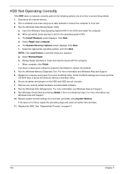
.... Run the Windows Vista Startup Repair Utility: a. Click Next. f. NOTE: Click Load Drivers if controller drives are set as the first boot device on page 41. 136 Chapter 4 Select Startup Repair. Select Repair your computer. Remove any key to start to locate and resolve issues...to correct the problem. 1. Startup Repair attempts to the operating system DVD. Click Next. If an issue is set correctly. 7. Run Windows Check Disk by entering chkdsk /r from a known good date using up-to-date software to resolve the problem. 4. If the issue is virus free. ...
.... Run the Windows Vista Startup Repair Utility: a. Click Next. f. NOTE: Click Load Drivers if controller drives are set as the first boot device on page 41. 136 Chapter 4 Select Startup Repair. Select Repair your computer. Remove any key to start to locate and resolve issues...to correct the problem. 1. Startup Repair attempts to the operating system DVD. Click Next. If an issue is set correctly. 7. Run Windows Check Disk by entering chkdsk /r from a known good date using up-to-date software to resolve the problem. 4. If the issue is virus free. ...
Service Guide
Page 164
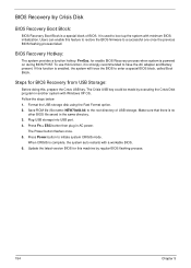
... one once the previous BIOS flashing process failed. The Crisis USB key could be made by executing the Crisis Disk program in the same directory. 3. It is strongly recommended to boot up the system with a workable BIOS. 6. If this function, it is used to have the AC adapter... and Battery present. Follow the steps below: 1. BIOS Recovery by Crisis Disk BIOS Recovery Boot Block: BIOS Recovery Boot Block is powered on during BIOS POST. Users can enable this , prepare the Crisis USB key. BIOS Recovery Hotkey: The system ...
... one once the previous BIOS flashing process failed. The Crisis USB key could be made by executing the Crisis Disk program in the same directory. 3. It is strongly recommended to boot up the system with a workable BIOS. 6. If this function, it is used to have the AC adapter... and Battery present. Follow the steps below: 1. BIOS Recovery by Crisis Disk BIOS Recovery Boot Block: BIOS Recovery Boot Block is powered on during BIOS POST. Users can enable this , prepare the Crisis USB key. BIOS Recovery Hotkey: The system ...
Service Guide
Page 255
..., 91 Replacing 93 B Battery Replacing 128 Battery Pack Removing 43 BIOS ROM type 15 vendor 15 BIOS Utility 21-29 Advanced 24 Boot 27 Exit 28 Navigating 21 Onboard Device Configuration 25 Power 27 Save and Exit 28 Security 24 System Security 28 Board Layout Top View...EasyTouch Failure 140 External Module Disassembly Flowchart 42 F Features 1 Flash Utility 29 FPC Cable Removing 86 FRU (Field Replaceable Unit) List 155 H Hard Disk Drive Removing 52 Replacing 121 HDTV Switch Failure 141 Hibernation mode hotkey 13 Hot Keys 11 I Indicators 9 Intermittent Problems 142 Internal Microphone Failure 135 ...
..., 91 Replacing 93 B Battery Replacing 128 Battery Pack Removing 43 BIOS ROM type 15 vendor 15 BIOS Utility 21-29 Advanced 24 Boot 27 Exit 28 Navigating 21 Onboard Device Configuration 25 Power 27 Save and Exit 28 Security 24 System Security 28 Board Layout Top View...EasyTouch Failure 140 External Module Disassembly Flowchart 42 F Features 1 Flash Utility 29 FPC Cable Removing 86 FRU (Field Replaceable Unit) List 155 H Hard Disk Drive Removing 52 Replacing 121 HDTV Switch Failure 141 Hibernation mode hotkey 13 Hot Keys 11 I Indicators 9 Intermittent Problems 142 Internal Microphone Failure 135 ...


