
Service Guide
Page 5
... information. 1. To better fit local market requirements and enhance product competitiveness, your regional office MAY have a DIFFERENT part number code to order FRU parts for Acer's "global" product offering. This Service Guide provides you with further technical details. 2. V These LOCALIZED FEATURES will not be covered in this printed Service Guide. For... note WHEN ORDERING FRU PARTS, that you with all technical information relating to -date information available on card, modem, or extra memory capability). In such cases, please contact your regional web or channel.
... information. 1. To better fit local market requirements and enhance product competitiveness, your regional office MAY have a DIFFERENT part number code to order FRU parts for Acer's "global" product offering. This Service Guide provides you with further technical details. 2. V These LOCALIZED FEATURES will not be covered in this printed Service Guide. For... note WHEN ORDERING FRU PARTS, that you with all technical information relating to -date information available on card, modem, or extra memory capability). In such cases, please contact your regional web or channel.
Service Guide
Page 35
... Password [ ] 2. Press Enter. Type the current password in the Enter New Password and Confirm New Password fields. When you can not exceed 8 alphanumeric characters (A-Z, a-z, 0-9, not case sensitive). The password length can opt to enable the Password on the screen. 3. Removing a Password Follow these steps as you are done, press F10 to...
... Password [ ] 2. Press Enter. Type the current password in the Enter New Password and Confirm New Password fields. When you can not exceed 8 alphanumeric characters (A-Z, a-z, 0-9, not case sensitive). The password length can opt to enable the Password on the screen. 3. Removing a Password Follow these steps as you are done, press F10 to...

Service Guide
Page 70
9. Starting at the top right side of the Lower Cover. 60 Chapter 3 Work along the front edge of the casing to the left as shown, then lift the Upper Cover clear of the cover, pry apart the Upper and Lower Covers as shown. Remove the seven (7) screws on the Upper Cover as shown. Step Upper Cover Size M2.5*5 Quantity 7 Screw Type 10.
9. Starting at the top right side of the Lower Cover. 60 Chapter 3 Work along the front edge of the casing to the left as shown, then lift the Upper Cover clear of the cover, pry apart the Upper and Lower Covers as shown. Remove the seven (7) screws on the Upper Cover as shown. Step Upper Cover Size M2.5*5 Quantity 7 Screw Type 10.
Service Guide
Page 82
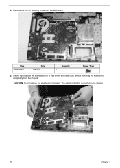
Remove the one (1) securing screw from the chassis. Lift the right edge of the mainboard first to the chassis. 72 Chapter 3 The mainboard is still connected to free it from the lower case, without removing the mainboard completely from the Mainboard. CAUTION: Do not remove the mainboard completely. 4. Step Mainboard Size M2.5*5 Quantity 1 Screw Type 5.
Remove the one (1) securing screw from the chassis. Lift the right edge of the mainboard first to the chassis. 72 Chapter 3 The mainboard is still connected to free it from the lower case, without removing the mainboard completely from the Mainboard. CAUTION: Do not remove the mainboard completely. 4. Step Mainboard Size M2.5*5 Quantity 1 Screw Type 5.
Service Guide
Page 116
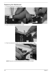
Connect the Bluetooth to the Bluetooth cable. 3. Connect the power cable. NOTE: Ensure the I/O ports are positioned correctly through the casing. 106 Chapter 3 Place the mainboard on a clean, dust-free surface. Replacing the Mainboard 1. Apply the adhesive tape to mainboard cable. 2.
Connect the Bluetooth to the Bluetooth cable. 3. Connect the power cable. NOTE: Ensure the I/O ports are positioned correctly through the casing. 106 Chapter 3 Place the mainboard on a clean, dust-free surface. Replacing the Mainboard 1. Apply the adhesive tape to mainboard cable. 2.
Service Guide
Page 136
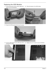
Secure the ODD bracket with the casing. 126 Chapter 3 Press the bezel into the ODD bay until it to the ODD Module. 3. Push the ODD Module into the tray, bottom edge first, to secure the Module. secure it is 5. Replace the one (1) screw to 2. Place the bracket on the ODD module. flush with the two (2) screws. 4. Replacing the ODD Module 1.
Secure the ODD bracket with the casing. 126 Chapter 3 Press the bezel into the ODD bay until it to the ODD Module. 3. Push the ODD Module into the tray, bottom edge first, to secure the Module. secure it is 5. Replace the one (1) screw to 2. Place the bracket on the ODD module. flush with the two (2) screws. 4. Replacing the ODD Module 1.
Service Guide
Page 137
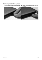
Push until the card clicks into the slot as shown. 2. Chapter 3 127 Insert the SD Dummy Card into place and is flush with the casing. Replacing the SD Dummy Card 1.
Push until the card clicks into the slot as shown. 2. Chapter 3 127 Insert the SD Dummy Card into place and is flush with the casing. Replacing the SD Dummy Card 1.
Service Guide
Page 140
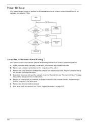
... directly into a known good electrical outlet. 4. If the Issue is properly connected to the computer and the electrical outlet. 2. Disconnect the power and open the casing to check the Thermal Unit (see "Online Support Information" on page 140) and fan airways are not necessary to boot the computer to the failure...
... directly into a known good electrical outlet. 4. If the Issue is properly connected to the computer and the electrical outlet. 2. Disconnect the power and open the casing to check the Thermal Unit (see "Online Support Information" on page 140) and fan airways are not necessary to boot the computer to the failure...

Service Guide
Page 171
CATEGORY Acer Description POWER CORD US 3 PIN POWER CORD EU 3 PIN POWER CORD AUS 3 PIN POWER CORD UK 3 PIN POWER CORD CHINA 3 PIN POWER CORD SWISS 3 PIN ... POWER CORD KOREA 3 PIN POWER CORD ISRAEL 3 PIN POWER CORD INDIA 3 PIN POWER CORD TWN 3 PIN POWER CORD ARGENTINA 3 PIN CASE/COVER/BRACKET ASSEMBLY UPPER CASE ASSY, INCL. TP/TP MYLAR LOWER CASE LOGIC LOWER DOOR 3G DOOR TP BRACKET HDD CARRIER AcerPN 27.TAVV5.001 27.TAVV5.002 27.TAVV5.003 27...
CATEGORY Acer Description POWER CORD US 3 PIN POWER CORD EU 3 PIN POWER CORD AUS 3 PIN POWER CORD UK 3 PIN POWER CORD CHINA 3 PIN POWER CORD SWISS 3 PIN ... POWER CORD KOREA 3 PIN POWER CORD ISRAEL 3 PIN POWER CORD INDIA 3 PIN POWER CORD TWN 3 PIN POWER CORD ARGENTINA 3 PIN CASE/COVER/BRACKET ASSEMBLY UPPER CASE ASSY, INCL. TP/TP MYLAR LOWER CASE LOGIC LOWER DOOR 3G DOOR TP BRACKET HDD CARRIER AcerPN 27.TAVV5.001 27.TAVV5.002 27.TAVV5.003 27...
Service Guide
Page 172
CATEGORY Acer Description CASE/COVER/BRACKET ASSEMBLY ODD BD COMBO MODULE ODD SUPER-MULTI DRIVE MODULE AcerPN 6M.PSV02.001 6M.PSV02.002 KEYBOARD 162 ODD BRACKET ODD BEZEL-SM ODD BEZEL-BD(HIGH SPEED) 33.PSV02.003 42.PSV02.003 42.PSV02.004 Keyboard ACER AC7T JV50 ...103KS Black US International w/ Hebrew Texture Keyboard ACER AC7T JV50 Internal 17 Standard 103KS Black Thailand Texture Keyboard ACER AC7T JV50 Internal 17 Standard 104KS Black UK Texture Keyboard ACER AC7T JV50 Internal 17 Standard 104KS Black German Texture Keyboard ACER AC7T JV50 Internal 17 Standard 104KS Black Swiss/G...
CATEGORY Acer Description CASE/COVER/BRACKET ASSEMBLY ODD BD COMBO MODULE ODD SUPER-MULTI DRIVE MODULE AcerPN 6M.PSV02.001 6M.PSV02.002 KEYBOARD 162 ODD BRACKET ODD BEZEL-SM ODD BEZEL-BD(HIGH SPEED) 33.PSV02.003 42.PSV02.003 42.PSV02.004 Keyboard ACER AC7T JV50 ...103KS Black US International w/ Hebrew Texture Keyboard ACER AC7T JV50 Internal 17 Standard 103KS Black Thailand Texture Keyboard ACER AC7T JV50 Internal 17 Standard 104KS Black UK Texture Keyboard ACER AC7T JV50 Internal 17 Standard 104KS Black German Texture Keyboard ACER AC7T JV50 Internal 17 Standard 104KS Black Swiss/G...


