Aspire 5335 / 5735 / 5735Z User's Guide EN
Page 10
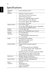
... 15.6" HD 1366 x 768 Mobile Intel® GL40/GM45 Express Chipset* 2.5" hard disk drive Optical drive option: • DVD-Super Multi double-layer drive 5-in-1 card reader Two built-in stereo speakers High-definition audio support MS-Sound compatible Built-in microphone Integrated Acer Crystal Eye webcam* WLAN: • Intel® Wireless WiFi Link 5100...
... 15.6" HD 1366 x 768 Mobile Intel® GL40/GM45 Express Chipset* 2.5" hard disk drive Optical drive option: • DVD-Super Multi double-layer drive 5-in-1 card reader Two built-in stereo speakers High-definition audio support MS-Sound compatible Built-in microphone Integrated Acer Crystal Eye webcam* WLAN: • Intel® Wireless WiFi Link 5100...
Aspire 5335 / 5735 / 5735Z Service Guide
Page 7
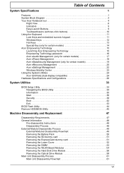
... (only for certain models 14 Acer Empowering Technology 15 Launching Acer Empowering Technology 15 Empowering Technology password 16 Acer eAudio Management (only for certain models 17 Acer ePower Management 18 Acer eDataSecurity Management (only for certain models 19 Acer eRecovery Management 20 Acer eSettings Management 22 Windows Mobility Center...51 Removing the Lower Cover 52 Removing the DIMM 53 Removing the WLAN Board Modules 54 Removing the Hard Disk Drive Module 56 Removing the Optical Drive Module 58 Main Unit Disassembly Process 61 Main Unit Disassembly Flowchart 61 VII
... (only for certain models 14 Acer Empowering Technology 15 Launching Acer Empowering Technology 15 Empowering Technology password 16 Acer eAudio Management (only for certain models 17 Acer ePower Management 18 Acer eDataSecurity Management (only for certain models 19 Acer eRecovery Management 20 Acer eSettings Management 22 Windows Mobility Center...51 Removing the Lower Cover 52 Removing the DIMM 53 Removing the WLAN Board Modules 54 Removing the Hard Disk Drive Module 56 Removing the Optical Drive Module 58 Main Unit Disassembly Process 61 Main Unit Disassembly Flowchart 61 VII
Aspire 5335 / 5735 / 5735Z Service Guide
Page 11
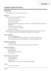
...Link 5100/5300* • Acer InviLink™ Nplify™ 802.11b/g/Draft-N* • Acer InviLink™ 802.11b/g* NOTE: Intel® Core™2 Duo T5800/T5900/T9400/P7350/P8400 for Aspire 5735Z; Intel® Pentium® dual-core T3200/T3400 for Aspire 5735; Chapter 1 System ... HD 1366 x 768 • Mobile Intel® GL40/GM45 Express Chipset (GM45 for Aspire 5735/5735Z/5335)* Storage subsystem • 2.5" hard disk drives • Optical drive options: •DVD-Super Multi double-layer drive • 5-in-1 card reader Special keys and controls • 105-/106-key keyboard ...
...Link 5100/5300* • Acer InviLink™ Nplify™ 802.11b/g/Draft-N* • Acer InviLink™ 802.11b/g* NOTE: Intel® Core™2 Duo T5800/T5900/T9400/P7350/P8400 for Aspire 5735Z; Intel® Pentium® dual-core T3200/T3400 for Aspire 5735; Chapter 1 System ... HD 1366 x 768 • Mobile Intel® GL40/GM45 Express Chipset (GM45 for Aspire 5735/5735Z/5335)* Storage subsystem • 2.5" hard disk drives • Optical drive options: •DVD-Super Multi double-layer drive • 5-in-1 card reader Special keys and controls • 105-/106-key keyboard ...
Aspire 5335 / 5735 / 5735Z Service Guide
Page 19
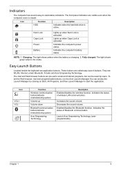
...LAN communication. The front panel indicators are called easy-launch buttons. Icon Function Description HDD Indicates when the hard disk drive is activated. Indicates the computer's battery status. Fully charged: The light shows green when in AC mode. Icon VOL+ .... Enables/disables the Bluetooth function. Easy-Launch Buttons Located beside the keyboard are : WLAN, Internet, email, Bluetooth, Arcade and Acer Empowering Technology. Charging: The light shows amber when the battery is closed. They are application buttons. Indicators The computer has several easy...
...LAN communication. The front panel indicators are called easy-launch buttons. Icon Function Description HDD Indicates when the hard disk drive is activated. Indicates the computer's battery status. Fully charged: The light shows green when in AC mode. Icon VOL+ .... Enables/disables the Bluetooth function. Easy-Launch Buttons Located beside the keyboard are : WLAN, Internet, email, Bluetooth, Arcade and Acer Empowering Technology. Charging: The light shows amber when the battery is closed. They are application buttons. Indicators The computer has several easy...
Aspire 5335 / 5735 / 5735Z Service Guide
Page 38
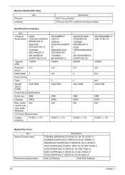
...5V(DC) +/- 5% Optical Disc Drive Item Vendor & model name Performance Specification Specification TOSHIBA SUPER-MULTI DRIVE DL 8X TS-L633A LF PIONEER SUPER-MULTI DRIVE 8X DVR-TD08RS LF PANASONIC SUPER-MULTI DRIVE DL 8X UJ-870A LF HLDS SUPER-MULTI DRIVE TRAY DL 8X GSA-T50N LF HLDS...Chapter 1 Wireless Module 802.11b/g Item Protocol Interface Specification 802.11b+g, Draft-N PCI bus (mini PCI socket for wireless module) Hard Disk Drive Interface Item Vendor & Model Name HGST HTS542512K9SA00 BRONCO-B LF SEAGATE ST9120817AS LF TOSHIBA MK1246GSX LF WD1200BEVS22UST0 ML125 LF Capacity (MB) ...
...5V(DC) +/- 5% Optical Disc Drive Item Vendor & model name Performance Specification Specification TOSHIBA SUPER-MULTI DRIVE DL 8X TS-L633A LF PIONEER SUPER-MULTI DRIVE 8X DVR-TD08RS LF PANASONIC SUPER-MULTI DRIVE DL 8X UJ-870A LF HLDS SUPER-MULTI DRIVE TRAY DL 8X GSA-T50N LF HLDS...Chapter 1 Wireless Module 802.11b/g Item Protocol Interface Specification 802.11b+g, Draft-N PCI bus (mini PCI socket for wireless module) Hard Disk Drive Interface Item Vendor & Model Name HGST HTS542512K9SA00 BRONCO-B LF SEAGATE ST9120817AS LF TOSHIBA MK1246GSX LF WD1200BEVS22UST0 ML125 LF Capacity (MB) ...
Aspire 5335 / 5735 / 5735Z Service Guide
Page 47
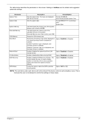
... server). Format: HH:MM:SS (hour:minute:second) System Time Sets the system date. The function allows the user to create a hidden partition on hard disc drive to store operation system and restore the system to control the settings in the system. Determines if Customer Logo will not be displayed or not...
... server). Format: HH:MM:SS (hour:minute:second) System Time Sets the system date. The function allows the user to create a hidden partition on hard disc drive to store operation system and restore the system to control the settings in the system. Determines if Customer Logo will not be displayed or not...
Aspire 5335 / 5735 / 5735Z Service Guide
Page 52
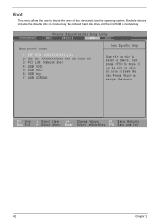
... -/+ Change Values F9 Setup Defaults Select Menu Enter Select Sub-Menu F10 Save and Exit 42 Chapter 2 Bootable devices includes the diskette drive in module bay, the onboard hard disk drive and the CD-ROM in module bay. Press to load the operating system. Information Phoenix SecureCore(tm) Setup Utility Main Security Boot...
... -/+ Change Values F9 Setup Defaults Select Menu Enter Select Sub-Menu F10 Save and Exit 42 Chapter 2 Bootable devices includes the diskette drive in module bay, the onboard hard disk drive and the CD-ROM in module bay. Press to load the operating system. Information Phoenix SecureCore(tm) Setup Utility Main Security Boot...

Aspire 5335 / 5735 / 5735Z Service Guide
Page 59
... CARD ExpressCard DUMMY CARD Captive Screwx4 Ax6 LOWER COVER Hx1 WLAN BOARD DIMM MODULES ODD MODULE Cx1 HDD MODULE OPTICAL DISK DRIVE Cx2 OPTICAL LOCKER BRACKET Dx2 HARD DISK BRACKET HARD DISK DRIVE Screw List Item A C D H Screw M2 x L8 M2 x L3 M3 x L4 M2 x L3 Color Black Silver Silver Black Part No. 86.00E34...
... CARD ExpressCard DUMMY CARD Captive Screwx4 Ax6 LOWER COVER Hx1 WLAN BOARD DIMM MODULES ODD MODULE Cx1 HDD MODULE OPTICAL DISK DRIVE Cx2 OPTICAL LOCKER BRACKET Dx2 HARD DISK BRACKET HARD DISK DRIVE Screw List Item A C D H Screw M2 x L8 M2 x L3 M3 x L4 M2 x L3 Color Black Silver Silver Black Part No. 86.00E34...
Aspire 5335 / 5735 / 5735Z Service Guide
Page 66
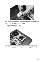
Removing the Hard Disk Drive Module 1. See "Removing the Battery Pack" on page 52. 3. See "Removing the Lower Cover" on page 50. 2. Step 1 Size (Quantity) M2 x L3 (1) Color Silver Torque 1.6 kgf-cm 56 Chapter 3 Remove the one screw (C) securing the hard disk drive module. NOTE: When attaching the antenna back to the WLAN board, make sure the cable are arranged properly. 6. Detach the WLAN board from the WLAN socket.
Removing the Hard Disk Drive Module 1. See "Removing the Battery Pack" on page 52. 3. See "Removing the Lower Cover" on page 50. 2. Step 1 Size (Quantity) M2 x L3 (1) Color Silver Torque 1.6 kgf-cm 56 Chapter 3 Remove the one screw (C) securing the hard disk drive module. NOTE: When attaching the antenna back to the WLAN board, make sure the cable are arranged properly. 6. Detach the WLAN board from the WLAN socket.
Aspire 5335 / 5735 / 5735Z Service Guide
Page 67
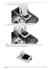
NOTE: To prevent damage to device, avoid pressing down on it or placing heavy objects on top of it from the connector. 5. Chapter 3 57 Lift the hard disk drive module and remove it . 6. Remove the two adhesive tape covering the two screws. Slide the hard disk drive module away from the hard disk drive bay. 4.
NOTE: To prevent damage to device, avoid pressing down on it or placing heavy objects on top of it from the connector. 5. Chapter 3 57 Lift the hard disk drive module and remove it . 6. Remove the two adhesive tape covering the two screws. Slide the hard disk drive module away from the hard disk drive bay. 4.
Aspire 5335 / 5735 / 5735Z Service Guide
Page 68
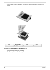
Remove the two screws (D) securing the hard disk to the bracket and remove the hard disk from the bracket. Step 1~2 Size (Quantity) M3 x L4 (2) Color Silver Removing the Optical Drive Module 1. Torque 3.0 kgf-cm 58 Chapter 3 See "Removing the Battery Pack" on page 52. See "Removing the Lower Cover" on page 50. 2. 7.
Remove the two screws (D) securing the hard disk to the bracket and remove the hard disk from the bracket. Step 1~2 Size (Quantity) M3 x L4 (2) Color Silver Removing the Optical Drive Module 1. Torque 3.0 kgf-cm 58 Chapter 3 See "Removing the Battery Pack" on page 52. See "Removing the Lower Cover" on page 50. 2. 7.
Aspire 5335 / 5735 / 5735Z Service Guide
Page 80
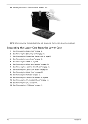
... SD dummy card" on page 52. 5. Separating the Upper Case from the base unit. See "Removing the Lower Cover" on page 51. 3. See "Removing the Hard Disk Drive Module" on page 62. 10. See "Removing the Middle Cover" on page 56. 8. See "Removing the CPU" on page 58. 9. See "Removing the Optical... Drive Module" on page 66. 14. See "Removing the CPU Heatsink Module" on page 51. 4. See "Removing the ExpressCard dummy card" on page 65. 13. See ...
... SD dummy card" on page 52. 5. Separating the Upper Case from the base unit. See "Removing the Lower Cover" on page 51. 3. See "Removing the Hard Disk Drive Module" on page 62. 10. See "Removing the Middle Cover" on page 56. 8. See "Removing the CPU" on page 58. 9. See "Removing the Optical... Drive Module" on page 66. 14. See "Removing the CPU Heatsink Module" on page 51. 4. See "Removing the ExpressCard dummy card" on page 65. 13. See ...
Aspire 5335 / 5735 / 5735Z Service Guide
Page 83
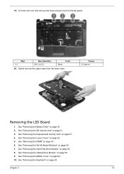
... card" on page 53. 6. See "Removing the WLAN Board Modules" on page 58. 9. Step 1~3 Size (Quantity) M2 x L4 (3) Color Black 20. See "Removing the Optical Drive Module" on page 54. 7. Torque 3.0 kgf-cm Removing the LED Board 1. Gently remove the upper case from the top panel. See "Removing the SD dummy... card" on page 50. 2. 19. See "Removing the Battery Pack" on page 51. 3. See "Removing the Hard Disk Drive Module" on page 63. See "Removing the Keyboard" on page 56. 8.
... card" on page 53. 6. See "Removing the WLAN Board Modules" on page 58. 9. Step 1~3 Size (Quantity) M2 x L4 (3) Color Black 20. See "Removing the Optical Drive Module" on page 54. 7. Torque 3.0 kgf-cm Removing the LED Board 1. Gently remove the upper case from the top panel. See "Removing the SD dummy... card" on page 50. 2. 19. See "Removing the Battery Pack" on page 51. 3. See "Removing the Hard Disk Drive Module" on page 63. See "Removing the Keyboard" on page 56. 8.
Aspire 5335 / 5735 / 5735Z Service Guide
Page 85
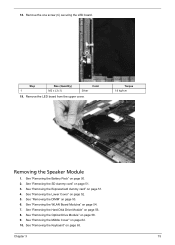
... Removing the Speaker Module 1. See "Removing the Battery Pack" on page 53. 6. See "Removing the DIMM" on page 50. 2. See "Removing the Optical Drive Module" on page 51. 4. 18. See "Removing the ExpressCard dummy card" on page 58. 9. See "Removing the Lower Cover" on page 56. 8. ...See "Removing the Hard Disk Drive Module" on page 52. 5. See "Removing the SD dummy card" on page 54. 7. Chapter 3 75 Remove the one screw (C) securing the LED board....
... Removing the Speaker Module 1. See "Removing the Battery Pack" on page 53. 6. See "Removing the DIMM" on page 50. 2. See "Removing the Optical Drive Module" on page 51. 4. 18. See "Removing the ExpressCard dummy card" on page 58. 9. See "Removing the Lower Cover" on page 56. 8. ...See "Removing the Hard Disk Drive Module" on page 52. 5. See "Removing the SD dummy card" on page 54. 7. Chapter 3 75 Remove the one screw (C) securing the LED board....
Aspire 5335 / 5735 / 5735Z Service Guide
Page 87
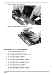
See "Removing the Battery Pack" on page 51. 4. See "Removing the ExpressCard dummy card" on page 50. 2. See "Removing the Optical Drive Module" on page 63. 11. See "Removing the Keyboard" on page 58. 9. 18. See "Removing the Lower Cover" on page 65. See "...Removing the CPU Heatsink Module" on page 52. 5. Chapter 3 77 Remove the speaker module from the latches. 19. Removing the Touchpad Module 1. See "Removing the Hard Disk Drive Module" on page 51. 3. See "Removing the SD dummy card" on page 56. 8. See "Removing the WLAN Board Modules" on page 53. 6. See...
See "Removing the Battery Pack" on page 51. 4. See "Removing the ExpressCard dummy card" on page 50. 2. See "Removing the Optical Drive Module" on page 63. 11. See "Removing the Keyboard" on page 58. 9. 18. See "Removing the Lower Cover" on page 65. See "...Removing the CPU Heatsink Module" on page 52. 5. Chapter 3 77 Remove the speaker module from the latches. 19. Removing the Touchpad Module 1. See "Removing the Hard Disk Drive Module" on page 51. 3. See "Removing the SD dummy card" on page 56. 8. See "Removing the WLAN Board Modules" on page 53. 6. See...
Aspire 5335 / 5735 / 5735Z Service Guide
Page 90
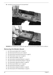
...glued to the upper case, only remove the touchpad board if it is defective. See "Removing the Battery Pack" on page 52. 5. See "Removing the Hard Disk Drive Module" on page 64. 12. See "Removing the Heatsink Fan Module" on page 56. 8. 20. See "Removing the Keyboard" on page 51. 3....Removing the Modem Board 1. See "Removing the Middle Cover" on page 58. 9. Carefully pry loose and remove the touch pad board. See "Removing the Optical Drive Module" on page 62. 10. See "Removing the ExpressCard dummy card" on page 54. 7. See "Removing the WLAN Board Modules" on page 51. 4....
...glued to the upper case, only remove the touchpad board if it is defective. See "Removing the Battery Pack" on page 52. 5. See "Removing the Hard Disk Drive Module" on page 64. 12. See "Removing the Heatsink Fan Module" on page 56. 8. 20. See "Removing the Keyboard" on page 51. 3....Removing the Modem Board 1. See "Removing the Middle Cover" on page 58. 9. Carefully pry loose and remove the touch pad board. See "Removing the Optical Drive Module" on page 62. 10. See "Removing the ExpressCard dummy card" on page 54. 7. See "Removing the WLAN Board Modules" on page 51. 4....
Aspire 5335 / 5735 / 5735Z Service Guide
Page 92
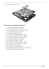
... Module" on page 80. 82 Chapter 3 See "Removing the CPU" on page 53. 6. See "Removing the DIMM" on page 66. 14. See "Removing the Optical Drive Module" on page 63. 11. See "Removing the Keyboard" on page 58. 9. See "Removing the ExpressCard dummy card" on page 50. 2. 18. See "Removing the...
... Module" on page 80. 82 Chapter 3 See "Removing the CPU" on page 53. 6. See "Removing the DIMM" on page 66. 14. See "Removing the Optical Drive Module" on page 63. 11. See "Removing the Keyboard" on page 58. 9. See "Removing the ExpressCard dummy card" on page 50. 2. 18. See "Removing the...
Aspire 5335 / 5735 / 5735Z Service Guide
Page 94
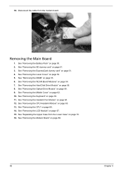
20. See "Removing the SD dummy card" on page 56. 8. See "Removing the Hard Disk Drive Module" on page 51. 3. See "Removing the Heatsink Fan Module" on page 51. 4. See "Removing the ExpressCard dummy card" on page 64. 12. See "Removing ... DIMM" on page 67. 15. See "Removing the LCD Module" on page 53. 6. See "Removing the Battery Pack" on page 58. 9. See "Removing the Optical Drive Module" on page 50. 2. See "Removing the Lower Cover" on page 65. 13. Carefully remove the main board. See "Removing the CPU Heatsink Module" on...
20. See "Removing the SD dummy card" on page 56. 8. See "Removing the Hard Disk Drive Module" on page 51. 3. See "Removing the Heatsink Fan Module" on page 51. 4. See "Removing the ExpressCard dummy card" on page 64. 12. See "Removing ... DIMM" on page 67. 15. See "Removing the LCD Module" on page 53. 6. See "Removing the Battery Pack" on page 58. 9. See "Removing the Optical Drive Module" on page 50. 2. See "Removing the Lower Cover" on page 65. 13. Carefully remove the main board. See "Removing the CPU Heatsink Module" on...
Aspire 5335 / 5735 / 5735Z Service Guide
Page 96
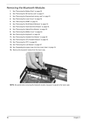
..." on page 56. 8. NOTE: Be careful when removing the bluetooth module, because it is glued to the lower case. 86 Chapter 3 See "Removing the Hard Disk Drive Module" on page 67. 15. See "Separating the Upper Case from the lower case. See "Removing the Middle Cover" on page 64. 12. See "Removing... Battery Pack" on page 51. 4. See "Removing the ExpressCard dummy card" on page 50. 2. See "Removing the DIMM" on page 58. 9. See "Removing the Optical Drive Module" on page 53. 6. See "Removing the Keyboard" on page 66. 14. See "Removing the CPU" on page 63. 11.
..." on page 56. 8. NOTE: Be careful when removing the bluetooth module, because it is glued to the lower case. 86 Chapter 3 See "Removing the Hard Disk Drive Module" on page 67. 15. See "Separating the Upper Case from the lower case. See "Removing the Middle Cover" on page 64. 12. See "Removing... Battery Pack" on page 51. 4. See "Removing the ExpressCard dummy card" on page 50. 2. See "Removing the DIMM" on page 58. 9. See "Removing the Optical Drive Module" on page 53. 6. See "Removing the Keyboard" on page 66. 14. See "Removing the CPU" on page 63. 11.
Aspire 5335 / 5735 / 5735Z Service Guide
Page 121
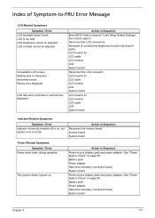
...-on , but system runs correctly Action in Sequence Power source (battery pack and power adapter). Battery pack Power adapter Hard drive & battery connection board System board Chapter 4 111 Battery pack Power adapter Hard drive & battery connection board System board Power source (battery pack and power adapter). Action in characters Abnormal screen Wrong color displayed...
...-on , but system runs correctly Action in Sequence Power source (battery pack and power adapter). Battery pack Power adapter Hard drive & battery connection board System board Chapter 4 111 Battery pack Power adapter Hard drive & battery connection board System board Power source (battery pack and power adapter). Action in characters Abnormal screen Wrong color displayed...


