Aspire 5335 / 5735 / 5735Z Service Guide
Page 7
...models 14 Acer Empowering Technology 15 Launching Acer Empowering Technology 15 Empowering Technology password 16 Acer eAudio Management (only for certain models 17 Acer ePower Management 18 Acer eDataSecurity Management (only for certain models 19 Acer eRecovery Management 20 Acer eSettings Management ... 45 Machine Disassembly and Replacement 47 Disassembly Requirements 47 General Information 48 Pre-disassembly Instructions 48 Disassembly Process 48 External Module Disassembly Process 49 External Modules Disassembly Flowchart 49 Removing the Battery Pack 50 Removing the ...
...models 14 Acer Empowering Technology 15 Launching Acer Empowering Technology 15 Empowering Technology password 16 Acer eAudio Management (only for certain models 17 Acer ePower Management 18 Acer eDataSecurity Management (only for certain models 19 Acer eRecovery Management 20 Acer eSettings Management ... 45 Machine Disassembly and Replacement 47 Disassembly Requirements 47 General Information 48 Pre-disassembly Instructions 48 Disassembly Process 48 External Module Disassembly Process 49 External Modules Disassembly Flowchart 49 Removing the Battery Pack 50 Removing the ...
Aspire 5335 / 5735 / 5735Z Service Guide
Page 105
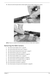
... the Web Camera 1. See "Removing the Middle Cover" on page 65. 9. Chapter 3 95 See "Removing the CPU Heatsink Module" on page 62. 7. See "Removing the Battery Pack" on page 52. 5. See "Removing the Lower Cover" on page 50. 2. 13. See "Removing the LCD panel with the tapes holding them in place... and right antenna cables together with the Brackets" on page 89. NOTE: There is no need to remove the antenna unless you really need to replace it. See "Removing the LCD Module" on page 51. 3.
... the Web Camera 1. See "Removing the Middle Cover" on page 65. 9. Chapter 3 95 See "Removing the CPU Heatsink Module" on page 62. 7. See "Removing the Battery Pack" on page 52. 5. See "Removing the Lower Cover" on page 50. 2. 13. See "Removing the LCD panel with the tapes holding them in place... and right antenna cables together with the Brackets" on page 89. NOTE: There is no need to remove the antenna unless you really need to replace it. See "Removing the LCD Module" on page 51. 3.
Aspire 5335 / 5735 / 5735Z Service Guide
Page 110
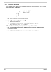
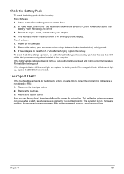
... System board. If the voltage is not corrected, see "Check the Battery Pack" on page 101. 100 Chapter 4 q If the voltage is not correct, replace the power adapter. 2. If the voltage is not correct, go to +20.5V Pin 2: 0V, Ground 1. q If the problem is within the range, do the ...
... System board. If the voltage is not corrected, see "Check the Battery Pack" on page 101. 100 Chapter 4 q If the voltage is not correct, replace the power adapter. 2. If the voltage is not correct, go to +20.5V Pin 2: 0V, Ground 1. q If the problem is within the range, do the ...
Aspire 5335 / 5735 / 5735Z Service Guide
Page 111
... room temperature. Repeat the steps 1 and 2, for a short time. No service actions are correct. 3. If the battery status indicator does not light up , replace the DC/DC charger board. This symptom is still less than 50% of time. Chapter 4 101 Power off the ... that has less than 7.5 Vdc after recharging, replace the battery. If the charge indicator still does not light up, replace the battery pack. Reconnect the touchpad cables. 2. Replace the system board. This helps you use a discharged battery pack or a battery pack that if the parameters shown in the screen...
... room temperature. Repeat the steps 1 and 2, for a short time. No service actions are correct. 3. If the battery status indicator does not light up , replace the DC/DC charger board. This symptom is still less than 50% of time. Chapter 4 101 Power off the ... that has less than 7.5 Vdc after recharging, replace the battery. If the charge indicator still does not light up, replace the battery pack. Reconnect the touchpad cables. 2. Replace the system board. This helps you use a discharged battery pack or a battery pack that if the parameters shown in the screen...
Aspire 5335 / 5735 / 5735Z Service Guide
Page 113
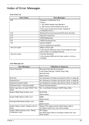
...Device Check" on page 98. BIOS ROM System board DIMM System board DIMM System board Replace RTC battery and Run BIOS Setup Utility to reconfigure system time, then reboot system. Battery critical LOW In this situation BIOS will shut down system, no message will show message...."Equipment Configuration Error") Memory Error at offset: nnnn System battery is specified. Unlock external keyboard Run "Load Default Settings" in BIOS Setup Utility. RTC battery Run BIOS Setup Utility to reconfigure system time, then reboot system. Replace and run Setup System CMOS checksum bad - CPU BIOS ...
...Device Check" on page 98. BIOS ROM System board DIMM System board DIMM System board Replace RTC battery and Run BIOS Setup Utility to reconfigure system time, then reboot system. Battery critical LOW In this situation BIOS will shut down system, no message will show message...."Equipment Configuration Error") Memory Error at offset: nnnn System battery is specified. Unlock external keyboard Run "Load Default Settings" in BIOS Setup Utility. RTC battery Run BIOS Setup Utility to reconfigure system time, then reboot system. Replace and run Setup System CMOS checksum bad - CPU BIOS ...
Aspire 5335 / 5735 / 5735Z Service Guide
Page 126
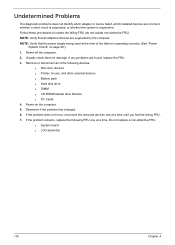
...). NOTE: Verify that all of the failure is inoperative. If the problem remains, replace the following devices: q Non-Acer devices q Printer, mouse, and other external devices q Battery pack q Hard disk drive q DIMM q CD-ROM/Diskette drive Module q PC Cards 4. Do not replace a non-defective FRU: q System board q LCD assembly 116 Chapter 4 Power-off the...
...). NOTE: Verify that all of the failure is inoperative. If the problem remains, replace the following devices: q Non-Acer devices q Printer, mouse, and other external devices q Battery pack q Hard disk drive q DIMM q CD-ROM/Diskette drive Module q PC Cards 4. Do not replace a non-defective FRU: q System board q LCD assembly 116 Chapter 4 Power-off the...
Aspire 5335 / 5735 / 5735Z Service Guide
Page 153
A AFLASH Utility 44 Antennas 94 Audio 30 B Battery Pack 50 BIOS 26 vendor 26 Version 26 BIOS Utility 33-44 Navigating 34 Onboard Device Configuration 39 Security 37, 38 System Security 43 Board ... Index 102 Euro 14 External CD-ROM Drive Check 98 External Module Disassembly Flowchart 49 F Index Features 1 Flash Utility 44 fpc cable 90 FRU (Field Replaceable Unit) List 121 H Hard disk 28 Hard Disk Drive Module 56 HDD 28 Hibernation mode hotkey 13 Hot Keys 11 I Indicators 9 Intermittent Problems 115 J Jumper...
A AFLASH Utility 44 Antennas 94 Audio 30 B Battery Pack 50 BIOS 26 vendor 26 Version 26 BIOS Utility 33-44 Navigating 34 Onboard Device Configuration 39 Security 37, 38 System Security 43 Board ... Index 102 Euro 14 External CD-ROM Drive Check 98 External Module Disassembly Flowchart 49 F Index Features 1 Flash Utility 44 fpc cable 90 FRU (Field Replaceable Unit) List 121 H Hard disk 28 Hard Disk Drive Module 56 HDD 28 Hibernation mode hotkey 13 Hot Keys 11 I Indicators 9 Intermittent Problems 115 J Jumper...


