Aspire 5733 Keyboard Removal - Acer
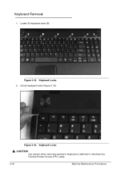
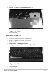
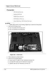
Aspire 5733 Keyboard Removal
Related Manual Pages


Related Videos

how to replace or remove keyboard in ACER Aspire 5733
Duration: 1:18
Total Views: 17,749
Duration: 1:18
Total Views: 17,749
Similar Questions

Disable Keyboard
How do I disable keyboard on acer aspire 5733 because the buttons are stuck and I am usin usb keyboa...
How do I disable keyboard on acer aspire 5733 because the buttons are stuck and I am usin usb keyboa...
(Posted by ernag71 9 years ago)

How To Video On Replacing Keyboard On Aspire 4743-4861
Need necessary steps on keyboard removal and install.
Need necessary steps on keyboard removal and install.
(Posted by justinpoky 10 years ago)


How To Put Back A Keyboard Key On A Acer Aspire 5733
(Posted by lacycatma 10 years ago)

How To Reset My Aspire 5733z-4614 Completly Remove Everything
i currently have a very big virus on my compruter and i want to completly reboot my compruter , i do...
i currently have a very big virus on my compruter and i want to completly reboot my compruter , i do...
(Posted by roxane1994 11 years ago)