Acer Aspire 5332 / 5732Z Series Service Guide
Page 11
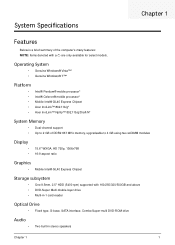
...• Acer InviLink™ Nplify™ 802.11b/g/Draft-N* System Memory • Dual-channel support • Up to 2 GB of the computer's many features: NOTE: Items denoted with 160/250/320/500GB and above • DVD-Super Multi double-layer drive • Multi-in-1 card-reader Optical ...DDR2 667 MHz memory, upgradeable to 4 GB using two soDIMM modules Display • • 15.6" WXGA, HD 720p, 1366x768 16:9 aspect ratio Graphics • Mobile Intel® GL40 Express Chipset Storage subsystem • One 9.5mm, 2.5" HDD (5400 rpm) supported with a (*) are only available for ...
...• Acer InviLink™ Nplify™ 802.11b/g/Draft-N* System Memory • Dual-channel support • Up to 2 GB of the computer's many features: NOTE: Items denoted with 160/250/320/500GB and above • DVD-Super Multi double-layer drive • Multi-in-1 card-reader Optical ...DDR2 667 MHz memory, upgradeable to 4 GB using two soDIMM modules Display • • 15.6" WXGA, HD 720p, 1366x768 16:9 aspect ratio Graphics • Mobile Intel® GL40 Express Chipset Storage subsystem • One 9.5mm, 2.5" HDD (5400 rpm) supported with a (*) are only available for ...
Acer Aspire 5332 / 5732Z Series Service Guide
Page 59
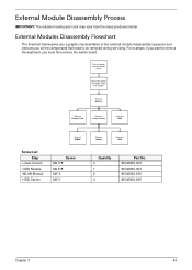
... from the mass produced model. External Module Disassembly Process IMPORTANT: The outside housing and color may vary from system Rem ove Battery Rem ove Dummy Card Rem ove Lower Covers Rem ove ODD Rem ove DIMMs Screw List Step Lower Covers ODD Module WLAN Module HDD Carrier Screw M2.5*8 M2.5*8 M2... 3 1 2 4 Part No. 86.N2802.003 86.N2802.003 86.N2802.006 86.N2802.005 Chapter 3 49 External Modules Disassembly Flowchart The flowchart below gives you a graphic representation of the external module disassembly sequence and instructs you must first remove the switch board.
... from the mass produced model. External Module Disassembly Process IMPORTANT: The outside housing and color may vary from system Rem ove Battery Rem ove Dummy Card Rem ove Lower Covers Rem ove ODD Rem ove DIMMs Screw List Step Lower Covers ODD Module WLAN Module HDD Carrier Screw M2.5*8 M2.5*8 M2... 3 1 2 4 Part No. 86.N2802.003 86.N2802.003 86.N2802.006 86.N2802.005 Chapter 3 49 External Modules Disassembly Flowchart The flowchart below gives you a graphic representation of the external module disassembly sequence and instructs you must first remove the switch board.


