Aspire 5680/5650/5630/5610/5610Z/3690 User's Guide
Page 5
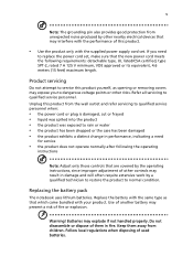
... following requirements: detachable type, UL listed/CSA certified, type SPT-2, rated 7 A 125 V minimum, VDE approved or its equivalent, 4.6 meters (15 feet) maximum length. Do not disassemble or dispose of them away from the wall outlet and refer servicing to qualified service personnel when: • the power cord or plug is damaged...
... following requirements: detachable type, UL listed/CSA certified, type SPT-2, rated 7 A 125 V minimum, VDE approved or its equivalent, 4.6 meters (15 feet) maximum length. Do not disassemble or dispose of them away from the wall outlet and refer servicing to qualified service personnel when: • the power cord or plug is damaged...
Aspire 5680/5650/5630/5610/5610Z/3690 User's Guide
Page 114
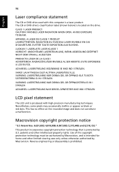
... viewing uses only unless otherwise authorized by U.S. The CD or DVD drive's classification label (shown below) is prohibited. EVITE EXPONERSE A LOS RAYOS. Reverse engineering or disassembly is located on the recorded image and does not constitute a malfunction. EVITTER TOUTE EXPOSITION AUX RAYONS. Macrovision copyright protection notice "U.S Patent Nos. 4,631,603; 4,819...
... viewing uses only unless otherwise authorized by U.S. The CD or DVD drive's classification label (shown below) is prohibited. EVITE EXPONERSE A LOS RAYOS. Reverse engineering or disassembly is located on the recorded image and does not constitute a malfunction. EVITTER TOUTE EXPOSITION AUX RAYONS. Macrovision copyright protection notice "U.S Patent Nos. 4,631,603; 4,819...
Service Guide
Page 63
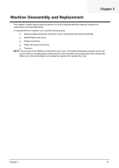
...Tweezers NOTE: The screws for maintenance and troubleshooting. Chapter 3 57 During the disassembly process, group the screws with the corresponding components to avoid mismatch when putting back the components. To disassemble the computer, you remove the stripe cover, please be careful not to scrape ...the cover. Chapter 3 Machine Disassembly and Replacement This chapter contains step-by-step procedures on how to disassemble the notebook computer for the different...
...Tweezers NOTE: The screws for maintenance and troubleshooting. Chapter 3 57 During the disassembly process, group the screws with the corresponding components to avoid mismatch when putting back the components. To disassemble the computer, you remove the stripe cover, please be careful not to scrape ...the cover. Chapter 3 Machine Disassembly and Replacement This chapter contains step-by-step procedures on how to disassemble the notebook computer for the different...

Service Guide
Page 64
Turn off the power to the system and all power and signal cables from the system. 3. General Information Before You Begin Before proceeding with the disassembly procedure, make sure that you do the following: 1. Unplug the AC adapter and all peripherals. 2. Remove the battery pack. 58 Chapter 3
Turn off the power to the system and all power and signal cables from the system. 3. General Information Before You Begin Before proceeding with the disassembly procedure, make sure that you do the following: 1. Unplug the AC adapter and all peripherals. 2. Remove the battery pack. 58 Chapter 3

Service Guide
Page 65
... want to remove the system board, you on the components that order. Disassembly Procedure Flowchart The flowchart on the succeeding page gives you a graphic representation on the entire disassembly sequence and instructs you must first remove the keyboard, then disassemble the inside assembly frame in that need to lower case assembly on upper...
... want to remove the system board, you on the components that order. Disassembly Procedure Flowchart The flowchart on the succeeding page gives you a graphic representation on the entire disassembly sequence and instructs you must first remove the keyboard, then disassemble the inside assembly frame in that need to lower case assembly on upper...
Service Guide
Page 72
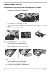
Disassembling the Main Unit Separate the Main Unit Into the Upper and the Lower Case Assembly 1. Disconnect the touchpad cable from the upper case carefully. Remove ... on the bottom as shown. 8. Remove two screws fastening the upper case assembly to the lower case assembly. 2. Disassembling the Upper Case Assembly 6. Remove the screws holding the touchpad bracket. 11. NOTE: Only Aspire 5650 series have media board. 9. Disconnect the LED board cable from the uppwer case. 66 Chapter 3 Take out the...
Disassembling the Main Unit Separate the Main Unit Into the Upper and the Lower Case Assembly 1. Disconnect the touchpad cable from the upper case carefully. Remove ... on the bottom as shown. 8. Remove two screws fastening the upper case assembly to the lower case assembly. 2. Disassembling the Upper Case Assembly 6. Remove the screws holding the touchpad bracket. 11. NOTE: Only Aspire 5650 series have media board. 9. Disconnect the LED board cable from the uppwer case. 66 Chapter 3 Take out the...

Service Guide
Page 73
Detach the modem cable from the main baord. Then disconnect the microphone cable from the lower case. 5. Detach the switch board from the main board then detach the modem board. 4. Disconnect the modem board from the main board. 2. Chapter 3 67 Detach the touchpad from the touchpad. 14. Disassembling the Lower Case Assembly 1. Disconnect the touchpad FFC. 13. Remove the screw fastening the modem board. 3. Then remove the touchpad FFC from the upper case. 12. Disconnect the speaker cable from the main board. 6.
Detach the modem cable from the main baord. Then disconnect the microphone cable from the lower case. 5. Detach the switch board from the main board then detach the modem board. 4. Disconnect the modem board from the main board. 2. Chapter 3 67 Detach the touchpad from the touchpad. 14. Disassembling the Lower Case Assembly 1. Disconnect the touchpad FFC. 13. Remove the screw fastening the modem board. 3. Then remove the touchpad FFC from the upper case. 12. Disconnect the speaker cable from the main board. 6.

Service Guide
Page 75
... cable from the inverter. 6. Remove the LCD right bracket. Remove the screw fastening the LCD inverter. 5. Tear off the tape fastening the LCD cable. 10. Disassembling the LCD Module 1. Remove the four screws holding the LCD bezel. 3. Remove the four screw caps as shown. 2.
... cable from the inverter. 6. Remove the LCD right bracket. Remove the screw fastening the LCD inverter. 5. Tear off the tape fastening the LCD cable. 10. Disassembling the LCD Module 1. Remove the four screws holding the LCD bezel. 3. Remove the four screw caps as shown. 2.

Service Guide
Page 77
Remove the optical bracket from the HDD bracket. Remove the three screws holding the optical bracket. 2. Chapter 3 71 Detach the HDD from the optical disk drive. Remove another two screws fastening the HDD bracket on one side. 2. Disassembling the ODD Module 1. Remove two screws hodling the HDD bracket on the other side. 3. Disassembling the External Modules Disassembling the HDD Module 1.
Remove the optical bracket from the HDD bracket. Remove the three screws holding the optical bracket. 2. Chapter 3 71 Detach the HDD from the optical disk drive. Remove another two screws fastening the HDD bracket on one side. 2. Disassembling the ODD Module 1. Remove two screws hodling the HDD bracket on the other side. 3. Disassembling the External Modules Disassembling the HDD Module 1.

Service Guide
Page 115
... CardBus 26 Chipsets 20 contrast hotkeys 16 Controllers 20 Core logic 20 CPU core voltage 20 I/O voltage 20 package 20 type 20 D DIMM Combinations 21 Disassembly Index Index Battery Pack 49 Procedure Flowchart 48 Display 2 display hotkeys 16 Display Standby Mode 29 DVD-ROM Interface 23, 24 E Environmental Requirements 29 Error...
... CardBus 26 Chipsets 20 contrast hotkeys 16 Controllers 20 Core logic 20 CPU core voltage 20 I/O voltage 20 package 20 type 20 D DIMM Combinations 21 Disassembly Index Index Battery Pack 49 Procedure Flowchart 48 Display 2 display hotkeys 16 Display Standby Mode 29 DVD-ROM Interface 23, 24 E Environmental Requirements 29 Error...


