User Manual
Page 5
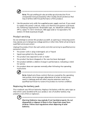
... following requirements: detachable type, UL listed/CSA certified, type SPT-2, rated 7 A 125 V minimum, VDE approved or its equivalent, 4.6 meters (15 feet) maximum length. Do not disassemble or dispose of them away from children. If you to qualified service personnel. Keep them in damage and will often require extensive work by a qualified...
... following requirements: detachable type, UL listed/CSA certified, type SPT-2, rated 7 A 125 V minimum, VDE approved or its equivalent, 4.6 meters (15 feet) maximum length. Do not disassemble or dispose of them away from children. If you to qualified service personnel. Keep them in damage and will often require extensive work by a qualified...

User Manual
Page 107
... AUSSETZEN PRODUCTO LÁSER DE LA CLASE I STRÅLEN. patents and other limited viewing uses only unless otherwise authorized by Macrovision. Reverse engineering or disassembly is produced with this copyright protection technology must be authorized by U.S. The CD or DVD drive's classification label (shown below) is located on the recorded...
... AUSSETZEN PRODUCTO LÁSER DE LA CLASE I STRÅLEN. patents and other limited viewing uses only unless otherwise authorized by Macrovision. Reverse engineering or disassembly is produced with this copyright protection technology must be authorized by U.S. The CD or DVD drive's classification label (shown below) is located on the recorded...

Service Guide
Page 2
Revision History Please refer to the table below for the updates made on page 1. Revise CCD module (digital camera) disassembling steps to Chapter 3 and Chapter 6 for Aspire 5560 series. II Add Radeon X1600 VGA chipset on Aspire 5540/5560 service guide. Date 2006/02/17 2006/4/1 2006/4/6 Chapter Chapter 3 and Chapter 6 Chapter 1 Chapter 3 Updates Add CCD module (camera) information to Chapter 3 for Aspire 5560 series.
Revision History Please refer to the table below for the updates made on page 1. Revise CCD module (digital camera) disassembling steps to Chapter 3 and Chapter 6 for Aspire 5560 series. II Add Radeon X1600 VGA chipset on Aspire 5540/5560 service guide. Date 2006/02/17 2006/4/1 2006/4/6 Chapter Chapter 3 and Chapter 6 Chapter 1 Chapter 3 Updates Add CCD module (camera) information to Chapter 3 for Aspire 5560 series.

Service Guide
Page 55
... Tweezers NOTE: The screws for maintenance and troubleshooting. Chapter 3 49 To disassemble the computer, you remove the stripe cover, please be careful not to scrape the cover. Chapter 3 Machine Disassembly and Replacement This chapter contains step-by-step procedures on how to avoid... mismatch when putting back the components. During the disassembly process, group the screws with the corresponding components to disassemble the notebook computer for the different...
... Tweezers NOTE: The screws for maintenance and troubleshooting. Chapter 3 49 To disassemble the computer, you remove the stripe cover, please be careful not to scrape the cover. Chapter 3 Machine Disassembly and Replacement This chapter contains step-by-step procedures on how to avoid... mismatch when putting back the components. During the disassembly process, group the screws with the corresponding components to disassemble the notebook computer for the different...

Service Guide
Page 56
General Information Before You Begin Before proceeding with the disassembly procedure, make sure that you do the following: 1. Unplug the AC adapter and all peripherals. 2. Remove the battery pack. 50 Chapter 3 Turn off the power to the system and all power and signal cables from the system. 3.
General Information Before You Begin Before proceeding with the disassembly procedure, make sure that you do the following: 1. Unplug the AC adapter and all peripherals. 2. Remove the battery pack. 50 Chapter 3 Turn off the power to the system and all power and signal cables from the system. 3.
Service Guide
Page 57
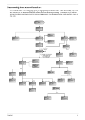
... Flowchart The flowchart on the succeeding page gives you a graphic representation on the entire disassembly sequence and instructs you must first remove the keyboard, then disassemble the inside assembly frame in that need to remove the system board, you on the components that order. Start Battery Middle Cover H*2 DIMM Cover Memory P*1 ...
... Flowchart The flowchart on the succeeding page gives you a graphic representation on the entire disassembly sequence and instructs you must first remove the keyboard, then disassemble the inside assembly frame in that need to remove the system board, you on the components that order. Start Battery Middle Cover H*2 DIMM Cover Memory P*1 ...
Service Guide
Page 64
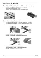
... the Bluetooth module as shown. 3. Turn over the lower case assembly to the lower case. 10. Remove the 15 screws on the bottom as shown. 8. Disassembling the Lower Case Assembly 4. Disassembling the Main Unit Separate the Main Unit Into the Upper and the Lower Case Assembly 1.
... the Bluetooth module as shown. 3. Turn over the lower case assembly to the lower case. 10. Remove the 15 screws on the bottom as shown. 8. Disassembling the Lower Case Assembly 4. Disassembling the Main Unit Separate the Main Unit Into the Upper and the Lower Case Assembly 1.

Service Guide
Page 66
Remove the heatsink from the LED board. 4. Disconnect the LED board FFC from the main board. 22. Use a flat-headed screwdriver to release the CPU socket lock. 23. The remove the LED board from the CPU socket carefully. Disconnect the touchpad FFC then remove it. 60 Chapter 3 Remove the two screws fastening the LED board. 2. Remove the CPU from the upper case assembly carefully. 3. Disassembling the Upper Case Assembly 1. 20. Remove the five screws fastening the heatsink. 21.
Remove the heatsink from the LED board. 4. Disconnect the LED board FFC from the main board. 22. Use a flat-headed screwdriver to release the CPU socket lock. 23. The remove the LED board from the CPU socket carefully. Disconnect the touchpad FFC then remove it. 60 Chapter 3 Remove the two screws fastening the LED board. 2. Remove the CPU from the upper case assembly carefully. 3. Disassembling the Upper Case Assembly 1. 20. Remove the five screws fastening the heatsink. 21.

Service Guide
Page 68
... inverter from the LCD cover, then disconnect the LCD cable from the LCD module. 4. Then remove the LCD hinges from the LCD panel as shown. 2. Disassembling the LCD Module 1. Remove the four screws holding the LCD to the LCD panel. 7.
... inverter from the LCD cover, then disconnect the LCD cable from the LCD module. 4. Then remove the LCD hinges from the LCD panel as shown. 2. Disassembling the LCD Module 1. Remove the four screws holding the LCD to the LCD panel. 7.

Service Guide
Page 70
Then detach the LCD bezel from the CCD bezel assembly. 8. Detach the CCD panel from the LCD module. 4. Disassembling the LCD Module (with video camera) 1. Remove the two screws fastening the LCD inverter. 5. NOTE: The edges of the CCD latch is very fragile, please ...
Then detach the LCD bezel from the CCD bezel assembly. 8. Detach the CCD panel from the LCD module. 4. Disassembling the LCD Module (with video camera) 1. Remove the two screws fastening the LCD inverter. 5. NOTE: The edges of the CCD latch is very fragile, please ...

Service Guide
Page 73
Disassembling the ODD Module 1. Chapter 3 67 Remove the two screws holding the ODD fix holder bracket. 2. Remove the HDD bracket. Reove the two screws fastening the ODD rail bracket then remove the rail bracket. Then remove the ODD fix holder bracket. 3. Disassembling the External Modules Disassembling the HDD Module 1. Remove the four screws fastening the HDD bracket. 2.
Disassembling the ODD Module 1. Chapter 3 67 Remove the two screws holding the ODD fix holder bracket. 2. Remove the HDD bracket. Reove the two screws fastening the ODD rail bracket then remove the rail bracket. Then remove the ODD fix holder bracket. 3. Disassembling the External Modules Disassembling the HDD Module 1. Remove the four screws fastening the HDD bracket. 2.


