Quick Start Guide
Page 10
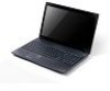
... drive access Lights up when the optical drive is off . Some keyless models are also available. Kensington lock slot Connects to USB 2.0 devices (e.g., USB mouse, USB camera). Insert the lock into the notch and turn the key to eject the optical drive tray when the computer is active. accepts CDs or DVDs...
... drive access Lights up when the optical drive is off . Some keyless models are also available. Kensington lock slot Connects to USB 2.0 devices (e.g., USB mouse, USB camera). Insert the lock into the notch and turn the key to eject the optical drive tray when the computer is active. accepts CDs or DVDs...
Quick Start Guide
Page 11
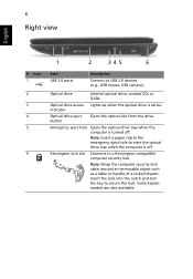
compartment Hard disk bay - Main Houses the computer's hard disk (secured with screws). 4 Battery lock Locks the battery in position. Environment • Temperature: • Operating: 5 °C to 35 °C • Non-operating: -20 °C to 65 °C • Humidity (non-condensing): • Operating: 20% to 80% • Non-operating: 20% to 80% English 9 Base view 1 2 4 3 # Icon 1 Item Battery bay Description Houses the computer's battery pack. 2 Battery release latch Releases the battery for removal. 3 Memory Houses the computer's main memory.
compartment Hard disk bay - Main Houses the computer's hard disk (secured with screws). 4 Battery lock Locks the battery in position. Environment • Temperature: • Operating: 5 °C to 35 °C • Non-operating: -20 °C to 65 °C • Humidity (non-condensing): • Operating: 20% to 80% • Non-operating: 20% to 80% English 9 Base view 1 2 4 3 # Icon 1 Item Battery bay Description Houses the computer's battery pack. 2 Battery release latch Releases the battery for removal. 3 Memory Houses the computer's main memory.
Service Guide
Page 7
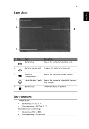
...System Specifications 1 Features 1 System Block Diagram 5 Your Acer Notebook tour 6 Front View 6 Closed Front View 7 Closed Rear View 7 Left View 8 Right View 8 Base View 9 Indicators 9 Touchpad Basics 10 Using the Keyboard 11 Lock Keys and embedded numeric keypad 11 Windows Keys 12 Hot... Keys 13 Hardware Specifications and Configurations 14 System Utilities 27 BIOS Setup Utility 27 Navigating the BIOS Utility 27 Aspire 5336 BIOS 28 Information 28 Main 29 Security ...
...System Specifications 1 Features 1 System Block Diagram 5 Your Acer Notebook tour 6 Front View 6 Closed Front View 7 Closed Rear View 7 Left View 8 Right View 8 Base View 9 Indicators 9 Touchpad Basics 10 Using the Keyboard 11 Lock Keys and embedded numeric keypad 11 Windows Keys 12 Hot... Keys 13 Hardware Specifications and Configurations 14 System Utilities 27 BIOS Setup Utility 27 Navigating the BIOS Utility 27 Aspire 5336 BIOS 28 Information 28 Main 29 Security ...
Service Guide
Page 12
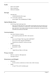
... DVD+RW, 5X DVD-RAM Communication • Acer Video Conference, featuring: • Acer Crystal Eye webcam with 1280 x 1024 resolution • WLAN: • Acer InviLink™ Nplify™ 802.11b/g/n Wi-Fi CERTIFIED™ • Acer InviLink™ 802.11b/g Wi-Fi CERTIFIED™...; • Supporting Acer SignalUp™ wireless technology • WPAN:1 • Bluetooth® 3.0+HS • Bluetooth® 2.1+EDR • LAN: • Gigabit Ethernet, Wake-on-LAN ready Privacy Control • BIOS user, supervisor, HDD passwords • Kensington lock slot Dimensions and Weight...
... DVD+RW, 5X DVD-RAM Communication • Acer Video Conference, featuring: • Acer Crystal Eye webcam with 1280 x 1024 resolution • WLAN: • Acer InviLink™ Nplify™ 802.11b/g/n Wi-Fi CERTIFIED™ • Acer InviLink™ 802.11b/g Wi-Fi CERTIFIED™...; • Supporting Acer SignalUp™ wireless technology • WPAN:1 • Bluetooth® 3.0+HS • Bluetooth® 2.1+EDR • LAN: • Gigabit Ethernet, Wake-on-LAN ready Privacy Control • BIOS user, supervisor, HDD passwords • Kensington lock slot Dimensions and Weight...
Service Guide
Page 18
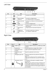
...2 3 4 5 6 8 Icon 1 2 34 5 6 Item USB 2.0 ports Optical drive Optical disk access indicator Optical drive eject button Emergency eject hole Kensington lock slot Description Connect to audio line-out devices (e.g. Note: Insert a paper clip into the notch and turn the key to a display device (e.g. Connects to eject... is off . Note: Wrap the computer security lock cable around an immovable object such as a table or handle of a locked drawer. Insert the lock into the emergency eject hole to a Kensington-compatible computer security lock. accepts CDs or DVDs. Lights up when the...
...2 3 4 5 6 8 Icon 1 2 34 5 6 Item USB 2.0 ports Optical drive Optical disk access indicator Optical drive eject button Emergency eject hole Kensington lock slot Description Connect to audio line-out devices (e.g. Note: Insert a paper clip into the notch and turn the key to a display device (e.g. Connects to eject... is off . Note: Wrap the computer security lock cable around an immovable object such as a table or handle of a locked drawer. Insert the lock into the emergency eject hole to a Kensington-compatible computer security lock. accepts CDs or DVDs. Lights up when the...
Service Guide
Page 19
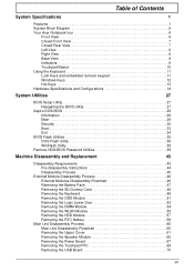
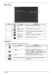
Battery release latch Hard disk bay Memory compartment Battery lock Releases the battery for removal. Communication indicator Indicates the computer's wireless connectivity device status. Indicators The computer has several easy-to-read ... with screws). Charging: The light shows amber when the battery is active. Houses the computer's main memory. Indicates when the hard disk drive is charging. 2. Locks the battery in AC mode. Base View 1 2 4 No. 1 2 3 4 3 Icon Item Battery bay Description Houses the computer's battery pack. Battery HDD Indicates the ...
Battery release latch Hard disk bay Memory compartment Battery lock Releases the battery for removal. Communication indicator Indicates the computer's wireless connectivity device status. Indicators The computer has several easy-to-read ... with screws). Charging: The light shows amber when the battery is active. Houses the computer's main memory. Indicates when the hard disk drive is charging. 2. Locks the battery in AC mode. Base View 1 2 4 No. 1 2 3 4 3 Icon Item Battery bay Description Houses the computer's battery pack. Battery HDD Indicates the ...

Service Guide
Page 21
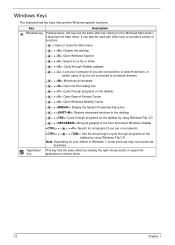
Chapter 1 11 When Num Lock is on, the embedded keypad is on, the contents of a text window scroll without moving the cursor. When Scroll Lock is in uppercase. Using the Keyboard The keyboard has full-sized keys and an embedded numeric keypad, separate cursor, lock, Windows, function and special keys. Lock key Caps Lock Scroll Lock Num Lock Description When Caps Lock is on and off. Lock Keys and embedded numeric keypad The keyboard has two lock keys which you can toggle on , all alphabetic characters typed are in numeric mode.
Chapter 1 11 When Num Lock is on, the embedded keypad is on, the contents of a text window scroll without moving the cursor. When Scroll Lock is in uppercase. Using the Keyboard The keyboard has full-sized keys and an embedded numeric keypad, separate cursor, lock, Windows, function and special keys. Lock key Caps Lock Scroll Lock Num Lock Description When Caps Lock is on and off. Lock Keys and embedded numeric keypad The keyboard has two lock keys which you can toggle on , all alphabetic characters typed are in numeric mode.
Service Guide
Page 22
... provide a variety of functions: < >: Open or close the Start menu < > + : Display the desktop < > + : Open Windows Explore < > + : Search for a file or folder < > + : Cycle through Sidebar gadgets < > + : Lock your computer (if you are connected to a network domain), or switch users (if you're not connected to a network domain) < > + : Minimizes all windows < > + : Open the...
... provide a variety of functions: < >: Open or close the Start menu < > + : Display the desktop < > + : Open Windows Explore < > + : Search for a file or folder < > + : Cycle through Sidebar gadgets < > + : Lock your computer (if you are connected to a network domain), or switch users (if you're not connected to a network domain) < > + : Minimizes all windows < > + : Open the...
Service Guide
Page 57
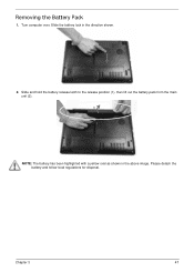
Slide and hold the battery release latch to the release position (1), then lift out the battery pack from the main unit (2). 2 1 NOTE: The battery has been highlighted with a yellow oval as shown in the direction shown. 2. Please detach the battery and follow local regulations for disposal. Slide the battery lock in the above image. Removing the Battery Pack 1. Chapter 3 47 Turn computer over.
Slide and hold the battery release latch to the release position (1), then lift out the battery pack from the main unit (2). 2 1 NOTE: The battery has been highlighted with a yellow oval as shown in the direction shown. 2. Please detach the battery and follow local regulations for disposal. Slide the battery lock in the above image. Removing the Battery Pack 1. Chapter 3 47 Turn computer over.
Service Guide
Page 59
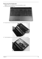
Turn the keyboard over on model. 1. Chapter 3 49 Pry up the center of the upper cover may vary depending on to the touchpad area to expose the FPC connector. Removing the Keyboard NOTE: The color of the keyboard and rotate it upward away from the upper cover. 3. Unlock the six (6) keyboard locks. 2.
Turn the keyboard over on model. 1. Chapter 3 49 Pry up the center of the upper cover may vary depending on to the touchpad area to expose the FPC connector. Removing the Keyboard NOTE: The color of the keyboard and rotate it upward away from the upper cover. 3. Unlock the six (6) keyboard locks. 2.
Service Guide
Page 60
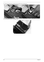
Lift the keyboard clear of the upper cover. 50 Chapter 3 Open the locking latch and disconnect the FPC from the mainboard. 5. 4.
Lift the keyboard clear of the upper cover. 50 Chapter 3 Open the locking latch and disconnect the FPC from the mainboard. 5. 4.
Service Guide
Page 79
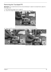
Lift the FFC to detach the adhesive securing the cable to the upper cover. 3. See "Removing the Upper Cover" on page 61. 2. Chapter 3 69 Release the FFC locking latch and disconnect the touchpad FFC from the connector. Removing the Touchpad FFC IMPORTANT: The touchpad board cannot be removed individually. To replace the touchpad board, replace the entire upper cover. 1.
Lift the FFC to detach the adhesive securing the cable to the upper cover. 3. See "Removing the Upper Cover" on page 61. 2. Chapter 3 69 Release the FFC locking latch and disconnect the touchpad FFC from the connector. Removing the Touchpad FFC IMPORTANT: The touchpad board cannot be removed individually. To replace the touchpad board, replace the entire upper cover. 1.
Service Guide
Page 89
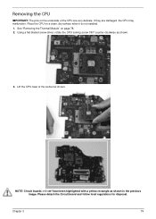
... delicate. Chapter 3 79 See "Removing the Thermal Module" on a clean, dry surface when it is not installed. 1. Using a flat-bladed screw driver, rotate the CPU locking screw 180° counter-clockwise as shown. Removing the CPU IMPORTANT: The pins on the underside of the socket as shown. 3. Lift the CPU clear...
... delicate. Chapter 3 79 See "Removing the Thermal Module" on a clean, dry surface when it is not installed. 1. Using a flat-bladed screw driver, rotate the CPU locking screw 180° counter-clockwise as shown. Removing the CPU IMPORTANT: The pins on the underside of the socket as shown. 3. Lift the CPU clear...
Service Guide
Page 121
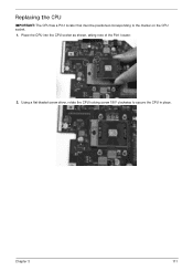
Using a flat-bladed screw driver, rotate the CPU locking screw 180° clockwise to the marker on the CPU socket. 1. Chapter 3 111 Replacing the CPU IMPORTANT: The CPU has a Pin1 locator that must be positioned corresponding to secure the CPU in place. Place the CPU into the CPU socket as shown, taking note of the Pin1 locator. 2.
Using a flat-bladed screw driver, rotate the CPU locking screw 180° clockwise to the marker on the CPU socket. 1. Chapter 3 111 Replacing the CPU IMPORTANT: The CPU has a Pin1 locator that must be positioned corresponding to secure the CPU in place. Place the CPU into the CPU socket as shown, taking note of the Pin1 locator. 2.
Service Guide
Page 127
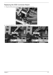
Place the ODD connector board into the lower cover using the board pin. 2. Chapter 3 117 Connect the ODD FFC to the mainboard and lock the connector. Replacing the ODD Connector Board 1.
Place the ODD connector board into the lower cover using the board pin. 2. Chapter 3 117 Connect the ODD FFC to the mainboard and lock the connector. Replacing the ODD Connector Board 1.
Service Guide
Page 130
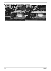
Connect the USB cable to the mainboard and lock the connector. 120 Chapter 3 4.
Connect the USB cable to the mainboard and lock the connector. 120 Chapter 3 4.
Service Guide
Page 131
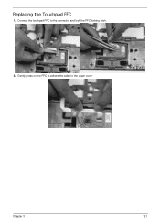
Gently press on the FFC to adhere the cable to the connector and lock the FFC locking latch. 2. Connect the touchpad FFC to the upper cover Chapter 3 121 Replacing the Touchpad FFC 1.
Gently press on the FFC to adhere the cable to the connector and lock the FFC locking latch. 2. Connect the touchpad FFC to the upper cover Chapter 3 121 Replacing the Touchpad FFC 1.
Service Guide
Page 135
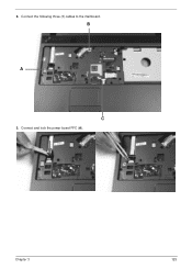
2. Chapter 3 125 Connect the following three (3) cables to the mainboard. Connect and lock the power board FFC (A). B A C 3.
2. Chapter 3 125 Connect the following three (3) cables to the mainboard. Connect and lock the power board FFC (A). B A C 3.
Service Guide
Page 136
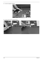
Connect the speaker cable (B). 5. Connect and lock the touchpad FFC (C). 126 Chapter 3 4.
Connect the speaker cable (B). 5. Connect and lock the touchpad FFC (C). 126 Chapter 3 4.
Service Guide
Page 142
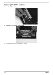
Repeat steps for the second DIMM module if present. 132 Chapter 3 Replacing the DIMM Modules 1. Insert the DIMM module in place. 3. Press down to lock the DIMM module in place. 2.
Repeat steps for the second DIMM module if present. 132 Chapter 3 Replacing the DIMM Modules 1. Insert the DIMM module in place. 3. Press down to lock the DIMM module in place. 2.


