
Aspire 3100 - 5100 - 5110 User's Guide
Page 5
Batteries may present a risk of fire or explosion. For more information on the Waste from children. Do not disassemble or dispose of electric shock from lightning, do not use non-compliant parts when adding or changing components. For safety reasons, do not...use and/or before servicing. • To avoid the remote risk of them away from Electrical and Electronics Equipment (WEEE) regulations, visit http://global.acer.com/about/environmental.htm. Telephone line safety • Disconnect all telephone lines from the equipment when not in fire. For more information, contact the...
Batteries may present a risk of fire or explosion. For more information on the Waste from children. Do not disassemble or dispose of electric shock from lightning, do not use non-compliant parts when adding or changing components. For safety reasons, do not...use and/or before servicing. • To avoid the remote risk of them away from Electrical and Electronics Equipment (WEEE) regulations, visit http://global.acer.com/about/environmental.htm. Telephone line safety • Disconnect all telephone lines from the equipment when not in fire. For more information, contact the...
Aspire 3100 - 5100 - 5110 User's Guide
Page 97
...;SER INVISIBLE AL SER ABIERTO. AVOID EXPOSURE TO BEAM. ADVARSEL: LASERSTRÅLING VEDÅBNING SE IKKE IND I STRÅLEN. Reverse engineering or disassembly is a laser product. APPAREIL A LASER DE CLASSE 1 PRODUIT LASERATTENTION: RADIATION DU FAISCEAU LASER INVISIBLE EN CAS D'OUVERTURE. EVITE EXPONERSE A LOS RAYOS. The CD or DVD...
...;SER INVISIBLE AL SER ABIERTO. AVOID EXPOSURE TO BEAM. ADVARSEL: LASERSTRÅLING VEDÅBNING SE IKKE IND I STRÅLEN. Reverse engineering or disassembly is a laser product. APPAREIL A LASER DE CLASSE 1 PRODUIT LASERATTENTION: RADIATION DU FAISCEAU LASER INVISIBLE EN CAS D'OUVERTURE. EVITE EXPONERSE A LOS RAYOS. The CD or DVD...
Aspire 3100 - 5100 - 5110 Service Guide
Page 8
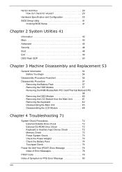
... 43 Advanced 45 Security 46 Boot 48 Exit 49 DOS Flash SOP 50 Chapter 3 Machine Disassembly and Replacement 53 General Information 54 Before You Begin 54 Disassembly Procedure Flowchart 55 Disassembly Procedure 57 Removing the Battery Pack 57 Removing the HDD Module 57 Removing the RAM Module/... Module/CPU 58 Removing the ODD Module 60 Removing the LCD Module from the Main Unit 61 Removing the Keyboard 62 Disassembling the Main Unit 63 Disassembling the LCD Module 68 Chapter 4 Troubleshooting 71 System Check Procedures 72 External Diskette Drive Check 72 External CD-ROM Drive...
... 43 Advanced 45 Security 46 Boot 48 Exit 49 DOS Flash SOP 50 Chapter 3 Machine Disassembly and Replacement 53 General Information 54 Before You Begin 54 Disassembly Procedure Flowchart 55 Disassembly Procedure 57 Removing the Battery Pack 57 Removing the HDD Module 57 Removing the RAM Module/... Module/CPU 58 Removing the ODD Module 60 Removing the LCD Module from the Main Unit 61 Removing the Keyboard 62 Disassembling the Main Unit 63 Disassembling the LCD Module 68 Chapter 4 Troubleshooting 71 System Check Procedures 72 External Diskette Drive Check 72 External CD-ROM Drive...
Aspire 3100 - 5100 - 5110 Service Guide
Page 62
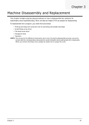
... be careful not to scrape the cover. Here, we take an Aspire 5110 as sample for the different components vary in size. During the disassembly process, group the screws with the corresponding components to disassemble the notebook for maintenance and troubleshooting. Chapter 3 Machine Disassembly and Replacement This chapter contains step-by-step procedures on how... conductive mat for preventing electrostatic discharge • Small Philips screw driver • Flat head screw driver • Hexagonal driver • Tweezers NOTE: The screws for disassembly. Chapter 3 53
... be careful not to scrape the cover. Here, we take an Aspire 5110 as sample for the different components vary in size. During the disassembly process, group the screws with the corresponding components to disassemble the notebook for maintenance and troubleshooting. Chapter 3 Machine Disassembly and Replacement This chapter contains step-by-step procedures on how... conductive mat for preventing electrostatic discharge • Small Philips screw driver • Flat head screw driver • Hexagonal driver • Tweezers NOTE: The screws for disassembly. Chapter 3 53
Aspire 3100 - 5100 - 5110 Service Guide
Page 63
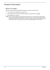
... flowchart. The screws vary in length. The system and all power and signal cables from the system are several types of screws together during service disassembling. If you have to make sure that: 1. Group the same type of screws used to secure the main unit. The battery pack is removed.... General Information Before You Begin Before proceeding with the disassembly procedure, you fasten the screws on the wrong location, the long screws may cause irrecoverable damage to the main board. 54 Chapter 3
... flowchart. The screws vary in length. The system and all power and signal cables from the system are several types of screws together during service disassembling. If you have to make sure that: 1. Group the same type of screws used to secure the main unit. The battery pack is removed.... General Information Before You Begin Before proceeding with the disassembly procedure, you fasten the screws on the wrong location, the long screws may cause irrecoverable damage to the main board. 54 Chapter 3
Aspire 3100 - 5100 - 5110 Service Guide
Page 64
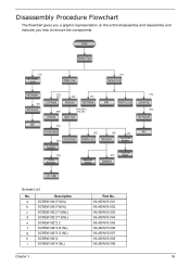
Description a SCREW M2.5*3(NL) b SCREW M2.5*6(NL) c SCREW M2.5*10(NL) d SCREW M2.5*15(NL) e SCREW M2*2.2 f SCREW M2*3-B (NL) g SCREW M2*3-S (NL) h SCREW M2*4 i SCREW M3*4 (NL) Part No. 86.ADWV5.001 86.ADWV5.002 86.ADWV5.003 86.ADWV5.004 86.ADWV5.005 86.ADWV5.006 86.ADWV5.007 86.ADWV5.008 86.ADWV5.009 Chapter 3 55 Screws List No. Disassembly Procedure Flowchart The flowchart gives you a graphic representation on the entire disassembly and reassembly and instructs you how to remove the components.
Description a SCREW M2.5*3(NL) b SCREW M2.5*6(NL) c SCREW M2.5*10(NL) d SCREW M2.5*15(NL) e SCREW M2*2.2 f SCREW M2*3-B (NL) g SCREW M2*3-S (NL) h SCREW M2*4 i SCREW M3*4 (NL) Part No. 86.ADWV5.001 86.ADWV5.002 86.ADWV5.003 86.ADWV5.004 86.ADWV5.005 86.ADWV5.006 86.ADWV5.007 86.ADWV5.008 86.ADWV5.009 Chapter 3 55 Screws List No. Disassembly Procedure Flowchart The flowchart gives you a graphic representation on the entire disassembly and reassembly and instructs you how to remove the components.
Aspire 3100 - 5100 - 5110 Service Guide
Page 66
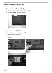
Pull the HDD module then lift the HDD module as the arrow indicates. 2. Disassembly Procedure Removing the Battery Pack 1. Removing the HDD Module 1. The battery pack will pop up then remove it. Chapter 3 57 Release the two screws fastening the HDD module cover. 2. Detach the HDD module cover. 3. Slide the battery lock to the end as the arrow indicates then detach the HDD module.
Pull the HDD module then lift the HDD module as the arrow indicates. 2. Disassembly Procedure Removing the Battery Pack 1. Removing the HDD Module 1. The battery pack will pop up then remove it. Chapter 3 57 Release the two screws fastening the HDD module cover. 2. Detach the HDD module cover. 3. Slide the battery lock to the end as the arrow indicates then detach the HDD module.

Aspire 3100 - 5100 - 5110 Service Guide
Page 69
Please skip the anterior steps of disassembly. Push the ODD module using a screwdriver as shown. 3. Removing the ODD Module If you just want to remove the anterior components. Remove the ODD module from the main unit. 60 Chapter 3 After you do not have to replace the ODD module, you remove the battery pack and the thermal module cover, follow the steps below. 1. Release the screw securing the ODD module. 2.
Please skip the anterior steps of disassembly. Push the ODD module using a screwdriver as shown. 3. Removing the ODD Module If you just want to remove the anterior components. Remove the ODD module from the main unit. 60 Chapter 3 After you do not have to replace the ODD module, you remove the battery pack and the thermal module cover, follow the steps below. 1. Release the screw securing the ODD module. 2.
Aspire 3100 - 5100 - 5110 Service Guide
Page 70
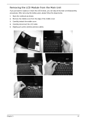
Chapter 3 61 Open the notebook as shown. 2. Slightly pull out the wireless antenna cables. Carefully detach the middle cover. 4. Remove the middle cover from the Main Unit If you just want to replace or check the LCD module, you can skip all the main unit disassembly procedures. Carefully disconnect the LCD cable. 5. Removing the LCD Module from the edge of the middle cover. 3. After removing the battery pack, please follow the steps below. 1.
Chapter 3 61 Open the notebook as shown. 2. Slightly pull out the wireless antenna cables. Carefully detach the middle cover. 4. Remove the middle cover from the Main Unit If you just want to replace or check the LCD module, you can skip all the main unit disassembly procedures. Carefully disconnect the LCD cable. 5. Removing the LCD Module from the edge of the middle cover. 3. After removing the battery pack, please follow the steps below. 1.
Aspire 3100 - 5100 - 5110 Service Guide
Page 71
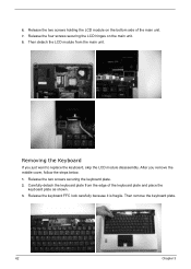
Release the two screws holding the LCD module on the main unit. 8. After you just want to replace the keyboard, skip the LCD module disassembly. Removing the Keyboard If you remove the middle cover, follow the steps below. 1. Carefully detach the keyboard plate from the main unit. Release the keyboard ...
Release the two screws holding the LCD module on the main unit. 8. After you just want to replace the keyboard, skip the LCD module disassembly. Removing the Keyboard If you remove the middle cover, follow the steps below. 1. Carefully detach the keyboard plate from the main unit. Release the keyboard ...
Aspire 3100 - 5100 - 5110 Service Guide
Page 72
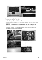
Release the four hexagonal screws securing the external VGA port and the DVI-D port. 4. Then detach the upper case from the main unit. Carefully release the media board FFC lock because it is fragile. Chapter 3 63 Then disconnect the media board FFC. 2. Release the two screws securing the upper case and the lower case on the bottom side. 3. Disassembling the Main Unit Separating the Upper Case and the Lower Case 1. Release the 12 screws securing the upper case and the lower case on the upper side. 5.
Release the four hexagonal screws securing the external VGA port and the DVI-D port. 4. Then detach the upper case from the main unit. Carefully release the media board FFC lock because it is fragile. Chapter 3 63 Then disconnect the media board FFC. 2. Release the two screws securing the upper case and the lower case on the bottom side. 3. Disassembling the Main Unit Separating the Upper Case and the Lower Case 1. Release the 12 screws securing the upper case and the lower case on the upper side. 5.
Aspire 3100 - 5100 - 5110 Service Guide
Page 77
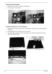
Tear off the tapes holding the LCD bezel. 2. Disassembling the LCD Module 1. Remove the four screw cushions on the LCD bezel then release the four screws holding the LVDS cable and the LCD cable then release the two screws securing the inverter board. 68 Chapter 3 Release the two screws securing the VGA heatsink. 2. Removing the VGA Heatsink 1. Carefully detach the LCD bezel from the LCD module. 3. Then detach the VGA heatsink.
Tear off the tapes holding the LCD bezel. 2. Disassembling the LCD Module 1. Remove the four screw cushions on the LCD bezel then release the four screws holding the LVDS cable and the LCD cable then release the two screws securing the inverter board. 68 Chapter 3 Release the two screws securing the VGA heatsink. 2. Removing the VGA Heatsink 1. Carefully detach the LCD bezel from the LCD module. 3. Then detach the VGA heatsink.


