Aspire 5040 / 3040 Service Guide
Page 18
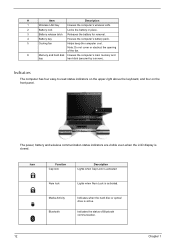
Note: Do not cover or obstruct the opening of Bluetooth communication. 12 Chapter 1 The power, battery and wireless communication status indicators are visible even when the LCD display is activated. Icon Function Cap lock Description Lights when Cap Lock is activated Num lock Lights when Num Lock is closed. Indicators The computer ...
Note: Do not cover or obstruct the opening of Bluetooth communication. 12 Chapter 1 The power, battery and wireless communication status indicators are visible even when the LCD display is activated. Icon Function Cap lock Description Lights when Cap Lock is activated Num lock Lights when Num Lock is closed. Indicators The computer ...

Aspire 5040 / 3040 Service Guide
Page 51
... remove the keyboard, then disassemble the inside assembly frame in that need to L case) RTC Battery Bluetooth Module H*3 DIMM/HDD Cover Memory N*4 HDD Module L*4 HDD Bracket HDD M*3 Upper Case Assembly N*3 Fan Upper Case Touchpad Assembly Speaker Set G*6 VGA Heatsink ... CPU Touchpad Bracket Touchpad ODD Module M2x2.5*2 ODD ODD Bracket Chapter 3 45 Start Battery Middle Cover Lower Case Assembly Lower Case Main Board Assembly H*2 Wireless LAN Cover O*1 Keyboard J*2 I*2 LCD Module Wireless LAN Cover ODD Module E*1 E*1(KB to U case) E*10 (U case to L case) F*3 ...
... remove the keyboard, then disassemble the inside assembly frame in that need to L case) RTC Battery Bluetooth Module H*3 DIMM/HDD Cover Memory N*4 HDD Module L*4 HDD Bracket HDD M*3 Upper Case Assembly N*3 Fan Upper Case Touchpad Assembly Speaker Set G*6 VGA Heatsink ... CPU Touchpad Bracket Touchpad ODD Module M2x2.5*2 ODD ODD Bracket Chapter 3 45 Start Battery Middle Cover Lower Case Assembly Lower Case Main Board Assembly H*2 Wireless LAN Cover O*1 Keyboard J*2 I*2 LCD Module Wireless LAN Cover ODD Module E*1 E*1(KB to U case) E*10 (U case to L case) F*3 ...

Aspire 5040 / 3040 Service Guide
Page 54
Remove the three screws fastening the DIMM/HDD cover. 2. Remove the two screws fastening the wireless LAN cover. 2. Removing the Wireless LAN Card 1. Pop out the wireless LAN card then remove it . 4. Detach the DIMM/HDD cover carefully. 3. Disconnect the main and the auxiliary antennae. 4. Remove four screws fastening the... HDD module. 5. Then detach the wireless LAN cover. 3. Pop out the memory then remove it . 48 Chapter 3 Pull the HDD module backwards then detach it. Removing the Memory...
Remove the three screws fastening the DIMM/HDD cover. 2. Remove the two screws fastening the wireless LAN cover. 2. Removing the Wireless LAN Card 1. Pop out the wireless LAN card then remove it . 4. Detach the DIMM/HDD cover carefully. 3. Disconnect the main and the auxiliary antennae. 4. Remove four screws fastening the... HDD module. 5. Then detach the wireless LAN cover. 3. Pop out the memory then remove it . 48 Chapter 3 Pull the HDD module backwards then detach it. Removing the Memory...

Aspire 5040 / 3040 Service Guide
Page 55
Open the notebook as shown. 2. Removing the ODD Module 1. Remove the screws fastening the ODD module as the impage shows. 2. Remove the screw holding the keyboard. 4. Turn over the keyboard as shown. . 3. Disconnect the keyboard cable then remove the keyboard. . 6. Removing the LCD Module 1. Detach the middle cover carefully as shown. 5. Use a flat headed screwdriver to push the ODD module outwards then remove it. Chapter 3 49 Pull out the wireless LAN antenna from the main unit as shown.
Open the notebook as shown. 2. Removing the ODD Module 1. Remove the screws fastening the ODD module as the impage shows. 2. Remove the screw holding the keyboard. 4. Turn over the keyboard as shown. . 3. Disconnect the keyboard cable then remove the keyboard. . 6. Removing the LCD Module 1. Detach the middle cover carefully as shown. 5. Use a flat headed screwdriver to push the ODD module outwards then remove it. Chapter 3 49 Pull out the wireless LAN antenna from the main unit as shown.
Aspire 5040 / 3040 Service Guide
Page 61
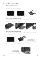
... the LCD inverter. 5. Take out the LCD assembly from the LCD module. 4. Remove the four screws fastening the LCD right bracket then remove the bracket. 11. Remove the four screw caps as shown. 2. Take out the LCD inverter from the LCD cover, then disconnect the LCD cable from the LCD then remove... the cable. Disconnect the inverter cable and remove the inverter. 7. Remove the four screws fastening the LCD left bracket then remove it. . 10. Remove the...
... the LCD inverter. 5. Take out the LCD assembly from the LCD module. 4. Remove the four screws fastening the LCD right bracket then remove the bracket. 11. Remove the four screw caps as shown. 2. Take out the LCD inverter from the LCD cover, then disconnect the LCD cable from the LCD then remove... the cable. Disconnect the inverter cable and remove the inverter. 7. Remove the four screws fastening the LCD left bracket then remove it. . 10. Remove the...

Aspire 5040 / 3040 Service Guide
Page 77
The system doesn't resume from the keyboard) Hard disk drive System board Press Fn+oand see if the computer enters hibernation mode. LCD cover switch System board See "Save to Disk (S4)" on page 28. Hard disk connection board Hard disk drive System board See "Save ...sound comes from actual size. Audio driver Speaker System board Speaker System board Action in Sequence See "Check the Battery Pack" on page 28. LCD cover switch System board Chapter 4 71 Power-Related Symptoms Symptom / Error Battery can't be charged Action in Sequence Power Management-Related Symptoms Symptom / Error...
The system doesn't resume from the keyboard) Hard disk drive System board Press Fn+oand see if the computer enters hibernation mode. LCD cover switch System board See "Save to Disk (S4)" on page 28. Hard disk connection board Hard disk drive System board See "Save ...sound comes from actual size. Audio driver Speaker System board Speaker System board Action in Sequence See "Check the Battery Pack" on page 28. LCD cover switch System board Chapter 4 71 Power-Related Symptoms Symptom / Error Battery can't be charged Action in Sequence Power Management-Related Symptoms Symptom / Error...

Aspire 5040 / 3040 User's Guide EN
Page 23
... # Icon Item 6 External display (VGA) port 7 Ventilation slots Description Connects to stay cool, even after prolonged use. Enable the computer to a display device (e.g., external monitor, LCD projector). Houses the computer's main memory and hard disk (secured with screws). Base view # Item 1 Wireless LAN bay 2 Battery lock 3 Battery release latch 4 Battery bay... fan 6 Memory and hard disk bay Description Houses the computer's wireless LAN. Locks the battery in position. Houses the computer's battery pack. Note: Do not cover or obstruct the opening of the fan.
... # Icon Item 6 External display (VGA) port 7 Ventilation slots Description Connects to stay cool, even after prolonged use. Enable the computer to a display device (e.g., external monitor, LCD projector). Houses the computer's main memory and hard disk (secured with screws). Base view # Item 1 Wireless LAN bay 2 Battery lock 3 Battery release latch 4 Battery bay... fan 6 Memory and hard disk bay Description Houses the computer's wireless LAN. Locks the battery in position. Houses the computer's battery pack. Note: Do not cover or obstruct the opening of the fan.


