
Service Guide
Page 7
Table of Contents System Specifications 1 Features 1 System Block Diagram 4 Your Acer Notebook tour 5 Front View 5 Left View 6 Right View 7 Rear View 7 Bottom View 7 Indicators 8 TouchPad Basics 9 Using the Keyboard 10... Utility 28 WinFlash Utility 30 Remove HDD/BIOS Password Utilities 31 Machine Disassembly and Replacement 37 Disassembly Requirements 37 General Information 38 Pre-disassembly Instructions 38 Disassembly Process 38 External Module Disassembly Process 39 External Modules Disassembly Flowchart 39 Removing the Battery Pack 40 Removing the SD dummy card ...
Table of Contents System Specifications 1 Features 1 System Block Diagram 4 Your Acer Notebook tour 5 Front View 5 Left View 6 Right View 7 Rear View 7 Bottom View 7 Indicators 8 TouchPad Basics 9 Using the Keyboard 10... Utility 28 WinFlash Utility 30 Remove HDD/BIOS Password Utilities 31 Machine Disassembly and Replacement 37 Disassembly Requirements 37 General Information 38 Pre-disassembly Instructions 38 Disassembly Process 38 External Module Disassembly Process 39 External Modules Disassembly Flowchart 39 Removing the Battery Pack 40 Removing the SD dummy card ...

Service Guide
Page 8
... the WiFi Antenna Cable 65 Removing the Right Speaker 66 Removing the LCD Module 67 Removing the DC-In Cable 68 LCD Module Disassembly Process 69 LCD Module Disassembly Flowchart 69 Removing the LCD Bezel 70 Removing the Camera Module 71 Removing the LCD Panel 72 Removing the FPC Cable 73 Removing...
... the WiFi Antenna Cable 65 Removing the Right Speaker 66 Removing the LCD Module 67 Removing the DC-In Cable 68 LCD Module Disassembly Process 69 LCD Module Disassembly Flowchart 69 Removing the LCD Bezel 70 Removing the Camera Module 71 Removing the LCD Panel 72 Removing the FPC Cable 73 Removing...

Service Guide
Page 53
... Replacement IMPORTANT:The outside housing and color may vary from the mass produced model. Disassembly Requirements To disassemble the computer, you need the following tools: • Wrist grounding strap and conductive mat for preventing electrostatic discharge &#...• Plastic flat screwdriver • Plastic tweezers NOTE: The screws for maintenance and troubleshooting. During the disassembly process, group the screws with the corresponding components to disassemble the notebook computer for the different components vary in size. Chapter 3 43 This chapter contains step-by-...
... Replacement IMPORTANT:The outside housing and color may vary from the mass produced model. Disassembly Requirements To disassemble the computer, you need the following tools: • Wrist grounding strap and conductive mat for preventing electrostatic discharge &#...• Plastic flat screwdriver • Plastic tweezers NOTE: The screws for maintenance and troubleshooting. During the disassembly process, group the screws with the corresponding components to disassemble the notebook computer for the different components vary in size. Chapter 3 43 This chapter contains step-by-...

Service Guide
Page 54
General Information Pre-disassembly Instructions Before proceeding with the disassembly procedure, make sure that order. Turn off the power to the system and all power and signal cables from the system...flat, stable surface. 4. Disassembly Process The disassembly process is divided into the following stages: • External module disassembly • Main unit disassembly The flowcharts provided in that you must first remove the keyboard, then disassemble the inside assembly frame in the succeeding disassembly sections illustrate the entire disassembly sequence. Observe the order ...
General Information Pre-disassembly Instructions Before proceeding with the disassembly procedure, make sure that order. Turn off the power to the system and all power and signal cables from the system...flat, stable surface. 4. Disassembly Process The disassembly process is divided into the following stages: • External module disassembly • Main unit disassembly The flowcharts provided in that you must first remove the keyboard, then disassemble the inside assembly frame in the succeeding disassembly sections illustrate the entire disassembly sequence. Observe the order ...

Service Guide
Page 55
...N1407.007 Chapter 3 45 Turn off system and peripherals power Disconnect power and signal cables from the mass produced model. External Modules Disassembly Flowchart The flowchart below gives you a graphic representation on the components that order. For example, if you want to remove the main... board, you on the entire disassembly sequence and instructs you must first remove the keyboard, then disassemble the inside assembly frame in that need to be removed during servicing. External Module Disassembly Process IMPORTANT:The outside housing and color may vary from...
...N1407.007 Chapter 3 45 Turn off system and peripherals power Disconnect power and signal cables from the mass produced model. External Modules Disassembly Flowchart The flowchart below gives you a graphic representation on the components that order. For example, if you want to remove the main... board, you on the entire disassembly sequence and instructs you must first remove the keyboard, then disassemble the inside assembly frame in that need to be removed during servicing. External Module Disassembly Process IMPORTANT:The outside housing and color may vary from...

Service Guide
Page 65
....PSR07.001 86.W4107.002 86.W4107.002 86.W4107.002 86.PSR07.001 86.PSR07.001 Chapter 3 55 Speaker Module L. Main Unit Disassembly Process Main Unit Disassembly Flowchart Remove external modules before proceeding Remove keyboard Remove upper cover Remove USB Board Remove Bluetooth Module Remove LED Board Remove Switch Board Remove...
....PSR07.001 86.W4107.002 86.W4107.002 86.W4107.002 86.PSR07.001 86.PSR07.001 Chapter 3 55 Speaker Module L. Main Unit Disassembly Process Main Unit Disassembly Flowchart Remove external modules before proceeding Remove keyboard Remove upper cover Remove USB Board Remove Bluetooth Module Remove LED Board Remove Switch Board Remove...

Service Guide
Page 87
LCD Module Disassembly Process LCD Module Disassembly Flowchart Remove LCD panel from main unit before preceeding Remove LCD bezel Remove camera module Remove LCD panel Remove FPC cable Remove microphone Remove WLAN antennas Remove LCD brackets Screw List Step LCD Bezel LCD Panel LCD Brackets Screw M2.5*4 M2.0*3 M2.5*3 Quantity 2 4 4 Part No. 86.PSR07.001 86.ARE07.002 86.TPK07.003 Chapter 3 77
LCD Module Disassembly Process LCD Module Disassembly Flowchart Remove LCD panel from main unit before preceeding Remove LCD bezel Remove camera module Remove LCD panel Remove FPC cable Remove microphone Remove WLAN antennas Remove LCD brackets Screw List Step LCD Bezel LCD Panel LCD Brackets Screw M2.5*4 M2.0*3 M2.5*3 Quantity 2 4 4 Part No. 86.PSR07.001 86.ARE07.002 86.TPK07.003 Chapter 3 77

Service Guide
Page 125
... the power and reboot the computer. 4. On this notebook model, switching between the internal display and the external display is selected. Remove the drives (see "Disassembly Process" on this model). If the computer boots correctly, add the devices one by removing the power cable and battery and holding down the power...
... the power and reboot the computer. 4. On this notebook model, switching between the internal display and the external display is selected. Remove the drives (see "Disassembly Process" on this model). If the computer boots correctly, add the devices one by removing the power cable and battery and holding down the power...
Service Guide
Page 126
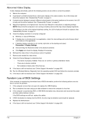
... CMOS battery. 2. Adjust the brightness to the previous version if updated. 7. See the User Manual for instructions on page 41. 3. See "Disassembly Process" on page 243. 10. If the Issue is still not resolved, see "Online Support Information" on the desktop and select Personalize´...time to correct the problem. 1. If extensive pixel damage is missing from the operating system DVD and follow the onscreen prompts. 11. See "Disassembly Process" on page 243. Minimize or close all Windows. b. c. Click and drag the Resolution slider to ensure the computer is still not ...
... CMOS battery. 2. Adjust the brightness to the previous version if updated. 7. See the User Manual for instructions on page 41. 3. See "Disassembly Process" on page 243. 10. If the Issue is still not resolved, see "Online Support Information" on the desktop and select Personalize´...time to correct the problem. 1. If extensive pixel damage is missing from the operating system DVD and follow the onscreen prompts. 11. See "Disassembly Process" on page 243. Minimize or close all Windows. b. c. Click and drag the Resolution slider to ensure the computer is still not ...

Service Guide
Page 130
.... 3. Run the Windows Disk Defragmenter. The System Recovery Options screen displays. f. Ensure all external devices. 2. If the issue is set correctly. 7. Select Startup Repair. See "Disassembly Process" on the Boot menu. 6. Disconnect all cables and jumpers on the HDD and ODD are set as the first boot device on page 41...
.... 3. Run the Windows Disk Defragmenter. The System Recovery Options screen displays. f. Ensure all external devices. 2. If the issue is set correctly. 7. Select Startup Repair. See "Disassembly Process" on the Boot menu. 6. Disconnect all cables and jumpers on the HDD and ODD are set as the first boot device on page 41...

Service Guide
Page 133
...ODD. d. e. Play a DVD movie f. a. If the drive works with the new cable, the original cable should be replaced. 4. See "Disassembly Process" on page 41. b. Repeat for broken connectors on the drive, motherboard, and cables. Test the drive using other ATA Devices shown if ...applicable. Try an alternate cable, if available. Restart the computer and press F2 to the ODD. b. c. See "Disassembly Process" on page 41. Check for broken connectors on the drive, motherboard, and cables. Chapter 4 123 Click Properties and select the Advanced...
...ODD. d. e. Play a DVD movie f. a. If the drive works with the new cable, the original cable should be replaced. 4. See "Disassembly Process" on page 41. b. Repeat for broken connectors on the drive, motherboard, and cables. Test the drive using other ATA Devices shown if ...applicable. Try an alternate cable, if available. Restart the computer and press F2 to the ODD. b. c. See "Disassembly Process" on page 41. Check for broken connectors on the drive, motherboard, and cables. Chapter 4 123 Click Properties and select the Advanced...


