
Aspire 4560 Service Guide
Page 3
... user input are shown in bold italics. CAUTION: Indicates a potential loss of an option, or completing a task. Example: At the prompt, type run -m Keyboard keys are shown in angle brackets (< >). Example: After entering data, press Enter. iii Conventions The following typographical conventions are used in this document: ...
... user input are shown in bold italics. CAUTION: Indicates a potential loss of an option, or completing a task. Example: At the prompt, type run -m Keyboard keys are shown in angle brackets (< >). Example: After entering data, press Enter. iii Conventions The following typographical conventions are used in this document: ...

Aspire 4560 Service Guide
Page 5
...Platform 1-5 System Memory 1-5 Display 1-5 Graphics 1-5 Storage Subsystem 1-6 Audio Subsystem 1-6 Communication 1-7 Privacy Control 1-7 Power Adapter and Battery 1-7 Keyboard and Pointing Device 1-8 I/O Ports 1-8 Software and Tools 1-8 Optional Items 1-10 Warranty 1-10 Dimensions and Weight 1-10 Environment 1-10 Notebook...1-11 Close Front View 1-13 Left View 1-14 Right View 1-15 Base View 1-16 Indicators 1-17 Touchpad Basics 1-18 Keyboard 1-18 Hotkeys 1-21 Special Keys 1-22 Specification Tables 1-25 CHAPTER 2 System Utilities BIOS Setup Utility 2-3 Navigating the BIOS ...
...Platform 1-5 System Memory 1-5 Display 1-5 Graphics 1-5 Storage Subsystem 1-6 Audio Subsystem 1-6 Communication 1-7 Privacy Control 1-7 Power Adapter and Battery 1-7 Keyboard and Pointing Device 1-8 I/O Ports 1-8 Software and Tools 1-8 Optional Items 1-10 Warranty 1-10 Dimensions and Weight 1-10 Environment 1-10 Notebook...1-11 Close Front View 1-13 Left View 1-14 Right View 1-15 Base View 1-16 Indicators 1-17 Touchpad Basics 1-18 Keyboard 1-18 Hotkeys 1-21 Special Keys 1-22 Specification Tables 1-25 CHAPTER 2 System Utilities BIOS Setup Utility 2-3 Navigating the BIOS ...

Aspire 4560 Service Guide
Page 6
... HDD Module 3-14 Removing the WLAN Module 3-16 Removing the Memory Modules 3-17 Main Unit Disassembly Process 3-19 Main Unit Disassembly Flowchart 3-19 Removing the Keyboard 3-20 Removing the Palmrest Module/Upper Cover 3-23 Removing the Speakers 3-27 Removing the Power Button Board 3-29 Removing the Touchpad Board 3-31 Removing the...
... HDD Module 3-14 Removing the WLAN Module 3-16 Removing the Memory Modules 3-17 Main Unit Disassembly Process 3-19 Main Unit Disassembly Flowchart 3-19 Removing the Keyboard 3-20 Removing the Palmrest Module/Upper Cover 3-23 Removing the Speakers 3-27 Removing the Power Button Board 3-29 Removing the Touchpad Board 3-31 Removing the...

Aspire 4560 Service Guide
Page 7
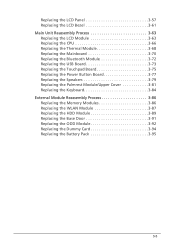
... 3-73 Replacing the Touchpad Board 3-75 Replacing the Power Button Board 3-77 Replacing the Speakers 3-79 Replacing the Palmrest Module/Upper Cover 3-81 Replacing the Keyboard 3-84 External Module Reassembly Process 3-86 Replacing the Memory Modules 3-86 Replacing the WLAN Module 3-87 Replacing the HDD Module 3-89 Replacing the Base Door...
... 3-73 Replacing the Touchpad Board 3-75 Replacing the Power Button Board 3-77 Replacing the Speakers 3-79 Replacing the Palmrest Module/Upper Cover 3-81 Replacing the Keyboard 3-84 External Module Reassembly Process 3-86 Replacing the Memory Modules 3-86 Replacing the WLAN Module 3-87 Replacing the HDD Module 3-89 Replacing the Base Door...

Aspire 4560 Service Guide
Page 8
No Display Issues 4-5 LCD Failure 4-7 Keyboard Failure 4-8 Touchpad Failure 4-9 Internal Speaker Failure 4-10 Microphone Failure 4-12 USB Failure 4-13 WLAN Failure 4-14 Bluetooth Failure 4-15 Card Reader Failure 4-16 Thermal Unit ... Codes 4-30 CHAPTER 5 Jumper and Connector Locations Mainboard Layout 5-3 Clearing Password Check and BIOS Recovery 5-5 Clearing the BIOS Passwords 5-5 Performing a BIOS Recovery 5-6 CHAPTER 6 FRU List Aspire 4560/4560G Exploded Diagram 6-4 Main Assembly 6-4 LCD Assembly 6-6 FRU List 6-7 viii
No Display Issues 4-5 LCD Failure 4-7 Keyboard Failure 4-8 Touchpad Failure 4-9 Internal Speaker Failure 4-10 Microphone Failure 4-12 USB Failure 4-13 WLAN Failure 4-14 Bluetooth Failure 4-15 Card Reader Failure 4-16 Thermal Unit ... Codes 4-30 CHAPTER 5 Jumper and Connector Locations Mainboard Layout 5-3 Clearing Password Check and BIOS Recovery 5-5 Clearing the BIOS Passwords 5-5 Performing a BIOS Recovery 5-6 CHAPTER 6 FRU List Aspire 4560/4560G Exploded Diagram 6-4 Main Assembly 6-4 LCD Assembly 6-6 FRU List 6-7 viii

Aspire 4560 Service Guide
Page 12
...1-5 System Memory 1-5 Display 1-5 Graphics 1-5 Storage Subsystem 1-6 Audio Subsystem 1-6 Communication 1-7 Privacy Control 1-7 Power Adapter and Battery 1-7 Keyboard and Pointing Device 1-8 I/O Ports 1-8 Software and Tools 1-8 Optional Items 1-10 Warranty 1-10 Dimensions and Weight 1-10 Environment 1-10...1-11 Close Front View 1-13 Left View 1-14 Right View 1-15 Base View 1-16 Indicators 1-17 Touchpad Basics 1-18 Keyboard 1-18 Hotkeys 1-21 Special Keys 1-22 Specification Tables 1-25 Computer Specifications 1-25 Processor 1-26 Processor Specifications 1-27 System Memory...
...1-5 System Memory 1-5 Display 1-5 Graphics 1-5 Storage Subsystem 1-6 Audio Subsystem 1-6 Communication 1-7 Privacy Control 1-7 Power Adapter and Battery 1-7 Keyboard and Pointing Device 1-8 I/O Ports 1-8 Software and Tools 1-8 Optional Items 1-10 Warranty 1-10 Dimensions and Weight 1-10 Environment 1-10...1-11 Close Front View 1-13 Left View 1-14 Right View 1-15 Base View 1-16 Indicators 1-17 Touchpad Basics 1-18 Keyboard 1-18 Hotkeys 1-21 Special Keys 1-22 Specification Tables 1-25 Computer Specifications 1-25 Processor 1-26 Processor Specifications 1-27 System Memory...

Aspire 4560 Service Guide
Page 18
Keyboard and Pointing Device 0 Keyboard 0 AC4T flat keyboard with international language support Overlay numeric keys Inverted "T" cursor keys Hotkeys for volume and brightness ...45) port DC-in jack (for the AC adapter) Software and Tools 0 Productivity 0 Acer Backup Manager Acer ePower Management Acer eRecovery Management Acer Updater Adobe® Flash® Player Adobe® Reader® Microsoft®...
Keyboard and Pointing Device 0 Keyboard 0 AC4T flat keyboard with international language support Overlay numeric keys Inverted "T" cursor keys Hotkeys for volume and brightness ...45) port DC-in jack (for the AC adapter) Software and Tools 0 Productivity 0 Acer Backup Manager Acer ePower Management Acer eRecovery Management Acer Updater Adobe® Flash® Player Adobe® Reader® Microsoft®...

Aspire 4560 Service Guide
Page 21
Turns the computer on and off. 4 Keyboard For entering data into your computer. 5 Touchpad Touch-sensitive pointing device which functions like a computer mouse. Open Front View No. 1 2 3 Icon Item Integrated webcam Display ...
Turns the computer on and off. 4 Keyboard For entering data into your computer. 5 Touchpad Touch-sensitive pointing device which functions like a computer mouse. Open Front View No. 1 2 3 Icon Item Integrated webcam Display ...
Aspire 4560 Service Guide
Page 28
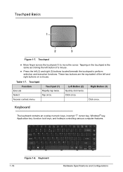
... (3) buttons located beneath the touchpad to move the cursor. Select Tap once. Touchpad Basics 0 Figure 1-7. Right Button (3) Click once. Keyboard Hardware Specifications and Configurations Tapping on a mouse. Table 1-7. Click once. Keyboard 0 The keyboard contains an overlay numeric keys, inverted "T" cursor key, Windows® key, Application key, function lock keys, and hotkeys controlling various...
... (3) buttons located beneath the touchpad to move the cursor. Select Tap once. Touchpad Basics 0 Figure 1-7. Right Button (3) Click once. Keyboard Hardware Specifications and Configurations Tapping on a mouse. Table 1-7. Click once. Keyboard 0 The keyboard contains an overlay numeric keys, inverted "T" cursor key, Windows® key, Application key, function lock keys, and hotkeys controlling various...

Aspire 4560 Service Guide
Page 29
...The state of the Num Lock is present, the Num Lock will have the following definitions: When On, the system boots with external keyboard/keypad Num Lock status On. Scroll Lock Fn+F12 When On, the screen moves one line up or down when pressing the up or down... cursor keys. Hardware Specifications and Configurations 1-19 Keyboard Lock Keys Table 1-8. If an external keyboard or keypad is not changed by the attachment/removal (hot plug) of the external keyboard/keypad. Num Lock affects the external keyboard/keypad only. Shift state is NOT required for all...
...The state of the Num Lock is present, the Num Lock will have the following definitions: When On, the system boots with external keyboard/keypad Num Lock status On. Scroll Lock Fn+F12 When On, the screen moves one line up or down when pressing the up or down... cursor keys. Hardware Specifications and Configurations 1-19 Keyboard Lock Keys Table 1-8. If an external keyboard or keypad is not changed by the attachment/removal (hot plug) of the external keyboard/keypad. Num Lock affects the external keyboard/keypad only. Shift state is NOT required for all...

Aspire 4560 Service Guide
Page 30
... provide a variety of Access Center window This key has the same effect as clicking the right mouse button; Windows-specific Keys Table 1-9. Windows Keys 0 The keyboard has two keys that perform Windows-specific functions. Windows-specific Keys Key Windows Logo key Application key Description Pressed alone, this key has the same...
... provide a variety of Access Center window This key has the same effect as clicking the right mouse button; Windows-specific Keys Table 1-9. Windows Keys 0 The keyboard has two keys that perform Windows-specific functions. Windows-specific Keys Key Windows Logo key Application key Description Pressed alone, this key has the same...

Aspire 4560 Service Guide
Page 39
...; Microsoft XP/Vista/Windows 7 logo program Microsoft SLP 1.0 support Microsoft OA 2.0 and 2.1 support Keyboard Item Specification Type AC4T flat keyboard Total number of keys 88 keys Windows logo key Yes Internal and external USB Yes keyboard work simultaneously? System BIOS Item BIOS vendor BIOS version BIOS ROM type BIOS ROM size...
...; Microsoft XP/Vista/Windows 7 logo program Microsoft SLP 1.0 support Microsoft OA 2.0 and 2.1 support Keyboard Item Specification Type AC4T flat keyboard Total number of keys 88 keys Windows logo key Yes Internal and external USB Yes keyboard work simultaneously? System BIOS Item BIOS vendor BIOS version BIOS ROM type BIOS ROM size...

Aspire 4560 Service Guide
Page 48
System Interrupt Specification Hardware IRQ IRQ0 IRQ1 IRQ2 IRQ3 IRQ5 IRQ6 IRQ7 IRQ8 IRQ9 IRQ10 IRQ11 IRQ12 IRQ13 IRQ14 IRQ15 System Function System timer Standard PS/2 keyboard Not in use Not in use Not in use Not in use Not in use System CMOS/real time clock Broadcom NetLink® BCM57785 xD Picture Card host controller Not in use Not in use Synaptics PS/2 port touchpad Numeric data processor Not in use Not in use 1-38 Hardware Specifications and Configurations
System Interrupt Specification Hardware IRQ IRQ0 IRQ1 IRQ2 IRQ3 IRQ5 IRQ6 IRQ7 IRQ8 IRQ9 IRQ10 IRQ11 IRQ12 IRQ13 IRQ14 IRQ15 System Function System timer Standard PS/2 keyboard Not in use Not in use Not in use Not in use Not in use System CMOS/real time clock Broadcom NetLink® BCM57785 xD Picture Card host controller Not in use Not in use Synaptics PS/2 port touchpad Numeric data processor Not in use Not in use 1-38 Hardware Specifications and Configurations
Aspire 4560 Service Guide
Page 54
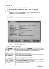
... number of the installed hard drive Model name of the installed optical device Current system BIOS version Current firmware version of the system VGA Current keyboard controller version Serial number of the computer's hardware information. Figure 2-1. Actual values can vary depending on the computer model. Hardware Information Table 2-1. NOTE: NOTE: The...
... number of the installed hard drive Model name of the installed optical device Current system BIOS version Current firmware version of the system VGA Current keyboard controller version Serial number of the computer's hardware information. Figure 2-1. Actual values can vary depending on the computer model. Hardware Information Table 2-1. NOTE: NOTE: The...
Aspire 4560 Service Guide
Page 68
... HDD Module 3-14 Removing the WLAN Module 3-16 Removing the Memory Modules 3-17 Main Unit Disassembly Process 3-19 Main Unit Disassembly Flowchart 3-19 Removing the Keyboard 3-20 Removing the Palmrest Module/Upper Cover 3-23 Removing the Speakers 3-27 Removing the Power Button Board 3-29 Removing the Touchpad Board 3-31 Removing the...
... HDD Module 3-14 Removing the WLAN Module 3-16 Removing the Memory Modules 3-17 Main Unit Disassembly Process 3-19 Main Unit Disassembly Flowchart 3-19 Removing the Keyboard 3-20 Removing the Palmrest Module/Upper Cover 3-23 Removing the Speakers 3-27 Removing the Power Button Board 3-29 Removing the Touchpad Board 3-31 Removing the...
Aspire 4560 Service Guide
Page 69
... 3-73 Replacing the Touchpad Board 3-75 Replacing the Power Button Board 3-77 Replacing the Speakers 3-79 Replacing the Palmrest Module/Upper Cover 3-81 Replacing the Keyboard 3-84 External Module Reassembly Process 3-86 Replacing the Memory Modules 3-86 Replacing the WLAN Module 3-87 Replacing the HDD Module 3-89 Replacing the Base Door...
... 3-73 Replacing the Touchpad Board 3-75 Replacing the Power Button Board 3-77 Replacing the Speakers 3-79 Replacing the Palmrest Module/Upper Cover 3-81 Replacing the Keyboard 3-84 External Module Reassembly Process 3-86 Replacing the Memory Modules 3-86 Replacing the WLAN Module 3-87 Replacing the HDD Module 3-89 Replacing the Base Door...
Aspire 4560 Service Guide
Page 73
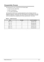
Table 3-1. Main Screw List Screw M2.5 × L6 M3 × L4 M2 × L3 M2.5 × L5 M2.5 × L4 Quantity 17 2 8 2 4 Acer Part Number 86.00E12.536 86.9A524.4R0 86.00F80.723 86.00F87.735 86.00H36.534 Machine Maintenance 3-7 Disassembly Process 0 The disassembly process is ... to any of the hardware components. Observe the order of the sequence to avoid damage to remove the main board, you must first remove the keyboard, then disassemble the inside assembly frame in the succeeding disassembly sections illustrate the entire disassembly sequence.
Table 3-1. Main Screw List Screw M2.5 × L6 M3 × L4 M2 × L3 M2.5 × L5 M2.5 × L4 Quantity 17 2 8 2 4 Acer Part Number 86.00E12.536 86.9A524.4R0 86.00F80.723 86.00F87.735 86.00H36.534 Machine Maintenance 3-7 Disassembly Process 0 The disassembly process is ... to any of the hardware components. Observe the order of the sequence to avoid damage to remove the main board, you must first remove the keyboard, then disassemble the inside assembly frame in the succeeding disassembly sections illustrate the entire disassembly sequence.

Aspire 4560 Service Guide
Page 85
...215; L6 M2 × L3 M2 × L3 M2.5 × L6 - Main Unit Disassembly Process 0 Main Unit Disassembly Flowchart 0 EXTERNAL MODULES KEYBOARD PALMREST MODULE/ UPPER COVER POWER BUTTON BOARD SPEAKER MODULE TOUCHPAD BOARD MAINBOARD LCD MODULE USB BOARD BLUETOOTH MODULE RTC BATTERY THERMAL MODULE CPU Figure 3-21.... M2.5 × L6 Quantity 2 3 7 4 1 1 5 4 Acer Part Number 86.00E12.536 86.00F80.723 86.00E12.536 86.00F80.723 86.00F80.723 86.00E12.536 86.00E12.536 Machine Maintenance...
...215; L6 M2 × L3 M2 × L3 M2.5 × L6 - Main Unit Disassembly Process 0 Main Unit Disassembly Flowchart 0 EXTERNAL MODULES KEYBOARD PALMREST MODULE/ UPPER COVER POWER BUTTON BOARD SPEAKER MODULE TOUCHPAD BOARD MAINBOARD LCD MODULE USB BOARD BLUETOOTH MODULE RTC BATTERY THERMAL MODULE CPU Figure 3-21.... M2.5 × L6 Quantity 2 3 7 4 1 1 5 4 Acer Part Number 86.00E12.536 86.00F80.723 86.00E12.536 86.00F80.723 86.00F80.723 86.00E12.536 86.00E12.536 Machine Maintenance...
Aspire 4560 Service Guide
Page 86
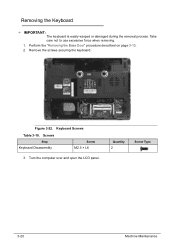
Quantity 2 Screw Type 3-20 Machine Maintenance Removing the Keyboard 0 + IMPORTANT: The keyboard is easily warped or damaged during the removal process. Screws Step Keyboard Disassembly Screw M2.5 × L6 3. Take care not to use excessive force when removing. 1. Figure 3-22. Keyboard Screws Table 3-10. Turn the computer over and open the LCD panel. Remove the screws securing the keyboard. Perform the "Removing the Base Door" procedure described on page 3-13. 2.
Quantity 2 Screw Type 3-20 Machine Maintenance Removing the Keyboard 0 + IMPORTANT: The keyboard is easily warped or damaged during the removal process. Screws Step Keyboard Disassembly Screw M2.5 × L6 3. Take care not to use excessive force when removing. 1. Figure 3-22. Keyboard Screws Table 3-10. Turn the computer over and open the LCD panel. Remove the screws securing the keyboard. Perform the "Removing the Base Door" procedure described on page 3-13. 2.

Aspire 4560 Service Guide
Page 87
Open the connector latch (b), and then disconnect the cable (c). Flip the keyboard over to push the latches on the top side of the keyboard. Figure 3-24. Figure 3-23. Keyboard Latches 5. Keyboard Machine Maintenance 3-21 Use a non-marring plastic flat-blade screwdriver to access the keyboard cable (a). 4.
Open the connector latch (b), and then disconnect the cable (c). Flip the keyboard over to push the latches on the top side of the keyboard. Figure 3-24. Figure 3-23. Keyboard Latches 5. Keyboard Machine Maintenance 3-21 Use a non-marring plastic flat-blade screwdriver to access the keyboard cable (a). 4.


