User Guide for Aspire 4530 / 4230 EN
Page 6
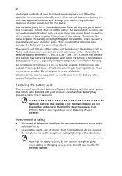
...parts when adding or changing components. Telephone line safety • Disconnect all telephone lines from the equipment when not in use any charger or battery that which could affect performance. Never use and/or before servicing. • To avoid the remote risk of electric ...not handled properly. vi discharged hundreds of times, but it will be susceptible to interference from the battery, which came bundled with Acer approved chargers designated for this equipment during lightning or thunderstorms. Warning! Accidental short-circuiting can occur when a metallic object such as a coin,...
...parts when adding or changing components. Telephone line safety • Disconnect all telephone lines from the equipment when not in use any charger or battery that which could affect performance. Never use and/or before servicing. • To avoid the remote risk of electric ...not handled properly. vi discharged hundreds of times, but it will be susceptible to interference from the battery, which came bundled with Acer approved chargers designated for this equipment during lightning or thunderstorms. Warning! Accidental short-circuiting can occur when a metallic object such as a coin,...

Service Guide
Page 14
System Block Diagram CPU CORE / VDDNB (ISL6265A) NB_CORE +1.1V (RT8202) +1.1V_NB (RT8202) DDR II SMDDR_VTERM 1.8VSUS(TPS51116REGR) SYSTEM POWER (ISL6237) SYSTEM CHARGER (ISL6251A) PCB STACK UP LAYER 1 : TOP LAYER 2 : GND LAYER 3 : IN1 LAYER 4 : IN2 LAYER 5 : VCC LAYER 6 : BOT DDRII-SODIMM1 DDRII-SODIMM2 DDRII 667/800 MHz DDRII ...
System Block Diagram CPU CORE / VDDNB (ISL6265A) NB_CORE +1.1V (RT8202) +1.1V_NB (RT8202) DDR II SMDDR_VTERM 1.8VSUS(TPS51116REGR) SYSTEM POWER (ISL6237) SYSTEM CHARGER (ISL6251A) PCB STACK UP LAYER 1 : TOP LAYER 2 : GND LAYER 3 : IN1 LAYER 4 : IN2 LAYER 5 : VCC LAYER 6 : BOT DDRII-SODIMM1 DDRII-SODIMM2 DDRII 667/800 MHz DDRII ...

Service Guide
Page 153
... 27 12 26 13 14 25 15 24 16 23 22 21 20 19 18 17 No. Description 1 E-Key Switch 12 Touch Pad Connector 23 Charger LED 2 LCD Power IC 13 +2.5V Power IC 24 Power LED 3 LCD/CCD Connector 14 EC controller 25 NewCard Connector 4 Internal Microphone 15 +3V...6 +1.1V Converter IC 17 Touch Pad Right Switch 28 NB_Core Converter IC 7 SW Board Connector 18 Touch Pad Left Switch 29 FAN Power IC 8 Charger Converter IC 19 BIOS 30 Function Board Connector 9 +1.8V, 0.9V Converter 20 +1.2V Power IC IC 31 LAN Transformer 10 Finger Board Connector 21 ...
... 27 12 26 13 14 25 15 24 16 23 22 21 20 19 18 17 No. Description 1 E-Key Switch 12 Touch Pad Connector 23 Charger LED 2 LCD Power IC 13 +2.5V Power IC 24 Power LED 3 LCD/CCD Connector 14 EC controller 25 NewCard Connector 4 Internal Microphone 15 +3V...6 +1.1V Converter IC 17 Touch Pad Right Switch 28 NB_Core Converter IC 7 SW Board Connector 18 Touch Pad Left Switch 29 FAN Power IC 8 Charger Converter IC 19 BIOS 30 Function Board Connector 9 +1.8V, 0.9V Converter 20 +1.2V Power IC IC 31 LAN Transformer 10 Finger Board Connector 21 ...


