Aspire 3650 / TravelMate 2450 Service Guide
Page 11
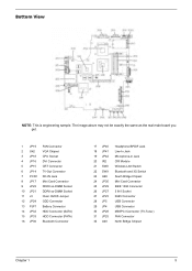
The image above may not be exactly the same as the real main board you get. 1 JP19 FAN Connector 2 U42 VGA Chipset 3 JP18 CPU Socket 4 JP16 DVI Connector 5 JP15 CRT Connector 6 JP14 TV-Out Connector 7 PCN1 DC-IN Jack 8 JP17 Mini Card Connector 9 JP22 DDRII so-DIMM Socket 10 ... Bluetooth and 3G Switch South Bridge Chipset Mini Card Connector IEEE 1394 Connector 5 IN1 Socket RJ45 Connector USB Connector USB Connector MINIPCI Connector (TV-Tuner) FAN Connector North Bridge Chipset Chapter 1 5 Bottom View NOTE: This is engineering sample.
The image above may not be exactly the same as the real main board you get. 1 JP19 FAN Connector 2 U42 VGA Chipset 3 JP18 CPU Socket 4 JP16 DVI Connector 5 JP15 CRT Connector 6 JP14 TV-Out Connector 7 PCN1 DC-IN Jack 8 JP17 Mini Card Connector 9 JP22 DDRII so-DIMM Socket 10 ... Bluetooth and 3G Switch South Bridge Chipset Mini Card Connector IEEE 1394 Connector 5 IN1 Socket RJ45 Connector USB Connector USB Connector MINIPCI Connector (TV-Tuner) FAN Connector North Bridge Chipset Chapter 1 5 Bottom View NOTE: This is engineering sample.
Aspire 3650 / TravelMate 2450 Service Guide
Page 65
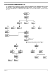
Start Battery Pack B*1 D*1 System Fan B*4 Thermal Module F*1 ODD Module CPU D*5 F*1 Thermal Door Memory Lower Case Assembly F*1 Mimi Cover F*2 HDD Door H*4 HDD Bracket HDD Middle Cover F*2 Keyboard C*2 LCD hinges to logic D*2 LCD hinges to logic C*2 on ...
Start Battery Pack B*1 D*1 System Fan B*4 Thermal Module F*1 ODD Module CPU D*5 F*1 Thermal Door Memory Lower Case Assembly F*1 Mimi Cover F*2 HDD Door H*4 HDD Bracket HDD Middle Cover F*2 Keyboard C*2 LCD hinges to logic D*2 LCD hinges to logic C*2 on ...
Aspire 3650 / TravelMate 2450 Service Guide
Page 68
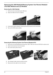
... main board. 4. Pull the HDD module outwards to take out the fan cable as shown. 5. M2*3(NL) for red circle; Removing the Memory/System Fan/Thermal Module/CPU 1. Disconnect the fan cable from the notebook. 3. Removing the HDD Module/Memory/System Fan/Thermal Module/ CPU/ODD Module and LCD Module Removing the HDD Module 1. Remove the...
... main board. 4. Pull the HDD module outwards to take out the fan cable as shown. 5. M2*3(NL) for red circle; Removing the Memory/System Fan/Thermal Module/CPU 1. Disconnect the fan cable from the notebook. 3. Removing the HDD Module/Memory/System Fan/Thermal Module/ CPU/ODD Module and LCD Module Removing the HDD Module 1. Remove the...
Aspire 3650 / TravelMate 2450 Service Guide
Page 69
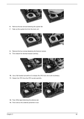
Chapter 3 63 Remove the two screws fastening the system fan. 7. Detach the CPU from the main unit. 8. Tear off the tape fastening the antenna set. 13. Take out the system fan from the CPU socket carefully. 12. Then remove the antenna protection cover. 6. Use a flat-headed screwdriver to release the CPU lock (Turn anti-clockwise). 11. Remove the four screws fastening the thermal module. 9. Then detach the thermal module carefully. 10.
Chapter 3 63 Remove the two screws fastening the system fan. 7. Detach the CPU from the main unit. 8. Tear off the tape fastening the antenna set. 13. Take out the system fan from the CPU socket carefully. 12. Then remove the antenna protection cover. 6. Use a flat-headed screwdriver to release the CPU lock (Turn anti-clockwise). 11. Remove the four screws fastening the thermal module. 9. Then detach the thermal module carefully. 10.
Aspire 3650 / TravelMate 2450 Service Guide
Page 98
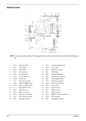
Bottom View NOTE: This is engineering sample. The image above may not be exactly the same as the real main board you get. 1 JP19 FAN Connector 2 U42 VGA Chipset 3 JP18 CPU Socket 4 JP16 DVI Connector 5 JP15 CRT Connector 6 JP14 TV-Out Connector 7 PCN1 DC-IN Jack 8 JP17 Mini Card Connector 9 JP22 DDRII so... Bluetooth and 3G Switch South Bridge Chipset Mini Card Connector IEEE 1394 Connector 5 IN1 Socket RJ45 Connector USB Connector USB Connector MINIPCI Connector (TV-Tuner) FAN Connector North Bridge Chipset 92 Chapter 5
Bottom View NOTE: This is engineering sample. The image above may not be exactly the same as the real main board you get. 1 JP19 FAN Connector 2 U42 VGA Chipset 3 JP18 CPU Socket 4 JP16 DVI Connector 5 JP15 CRT Connector 6 JP14 TV-Out Connector 7 PCN1 DC-IN Jack 8 JP17 Mini Card Connector 9 JP22 DDRII so... Bluetooth and 3G Switch South Bridge Chipset Mini Card Connector IEEE 1394 Connector 5 IN1 Socket RJ45 Connector USB Connector USB Connector MINIPCI Connector (TV-Tuner) FAN Connector North Bridge Chipset 92 Chapter 5
Aspire 3650 / TravelMate 2450 Service Guide
Page 112
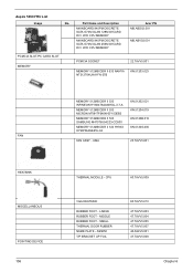
... G73M GLAN 128M W/CARD DVI W/O CPU MEMORY MAINBOARD 945PM DISCRETE SATA G73M GLAN 256M W/CARD DVI W/O CPU MEMORY PCMCIA SOCKET MEMORY 512MB DDR II 533 NANYA NT512T64UHA1FN-37B Acer PN MB.ABD02.001 MB.ABV02.001...II 533 SAMSUNG M470T6554CZ3-CD500 KN.5120B.015 MEMORY 512MB DDR II 533 HYNIX HYMP564S64P6-C4 KN.5120G.005 FAN FAN ASSY - LARGE RUBBER FOOT - MIDDLE RUBBER FOOT - AS5650 T/P BRACKET UP FOIL 60.TAVV5.010 ....TAVV5.007 40.A94V5.001 47.TAVV5.008 Chapter 6 CPU 60.TAVV5.009 VGA HEATSINK RUBBER FOOT - UMA 23.TAVV5.001 HEATSINK MISCELLANEOUS POINTING DEVICE 106 THERMAL MODULE...
... G73M GLAN 128M W/CARD DVI W/O CPU MEMORY MAINBOARD 945PM DISCRETE SATA G73M GLAN 256M W/CARD DVI W/O CPU MEMORY PCMCIA SOCKET MEMORY 512MB DDR II 533 NANYA NT512T64UHA1FN-37B Acer PN MB.ABD02.001 MB.ABV02.001...II 533 SAMSUNG M470T6554CZ3-CD500 KN.5120B.015 MEMORY 512MB DDR II 533 HYNIX HYMP564S64P6-C4 KN.5120G.005 FAN FAN ASSY - LARGE RUBBER FOOT - MIDDLE RUBBER FOOT - AS5650 T/P BRACKET UP FOIL 60.TAVV5.010 ....TAVV5.007 40.A94V5.001 47.TAVV5.008 Chapter 6 CPU 60.TAVV5.009 VGA HEATSINK RUBBER FOOT - UMA 23.TAVV5.001 HEATSINK MISCELLANEOUS POINTING DEVICE 106 THERMAL MODULE...


