Aspire 5050 / 3050 Service Guide
Page 71
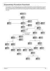
Start Battery Middle Cover H*2 DIMM Cover Memory P*1 Keyboard ODD Module E*1 J*2 on bottom side K*2 on top side LCD Module E*1 on upper case assemby E*12 on bottom side F*3 on bottom side A*2 on the components that order. For example, if you want to be ... you must first remove the keyboard, then disassemble the inside assembly frame in that need to remove the system board, you on rear side H*3 HDD Cover Wireless LAN Card O*4 HDD Module M*4 HDD Bracket HDD Lower Case *2 Speaker Set Lower Case Assembly O*2 Main Board Assembly RTC Battery Bluetooth Module Upper Case...
Start Battery Middle Cover H*2 DIMM Cover Memory P*1 Keyboard ODD Module E*1 J*2 on bottom side K*2 on top side LCD Module E*1 on upper case assemby E*12 on bottom side F*3 on bottom side A*2 on the components that order. For example, if you want to be ... you must first remove the keyboard, then disassemble the inside assembly frame in that need to remove the system board, you on rear side H*3 HDD Cover Wireless LAN Card O*4 HDD Module M*4 HDD Bracket HDD Lower Case *2 Speaker Set Lower Case Assembly O*2 Main Board Assembly RTC Battery Bluetooth Module Upper Case...

Aspire 5050 / 3050 Service Guide
Page 74
... Detach the RAM cover from the main unit. Remove the screw holding the HDD module as shown. 4. Then disconnect the entire HDD module from the main unit. 3. Removing the HDD Module/the Memory/the Wireless LAN Card/the Modem Board/the ODD Module and the LCD Module Removing the HDD... Module 1. Disconnnect the main and auxiliary wireless antennae from the wireless LAN card. 5. Remove the two screws fastening the HDD cover. 2. Remove the two screws fastening the RAM cover. 2. Remove the two screws fastening the wirless ...
... Detach the RAM cover from the main unit. Remove the screw holding the HDD module as shown. 4. Then disconnect the entire HDD module from the main unit. 3. Removing the HDD Module/the Memory/the Wireless LAN Card/the Modem Board/the ODD Module and the LCD Module Removing the HDD... Module 1. Disconnnect the main and auxiliary wireless antennae from the wireless LAN card. 5. Remove the two screws fastening the HDD cover. 2. Remove the two screws fastening the RAM cover. 2. Remove the two screws fastening the wirless ...

Aspire 5050 / 3050 Service Guide
Page 75
... the ODD module outwards then remove it. Chapter 3 67 Removing the LCD Module (including Keyboard) 1. Detach the modem board from the main unit. Open the LCD 180 degree as shown. 8. Carefully detach the keyboard cover from the main board then disconnect the modem board cable. Remove one ...screw holding the keyboard cover to the main board as shown. 3. Remove the wireless LAN ...
... the ODD module outwards then remove it. Chapter 3 67 Removing the LCD Module (including Keyboard) 1. Detach the modem board from the main unit. Open the LCD 180 degree as shown. 8. Carefully detach the keyboard cover from the main board then disconnect the modem board cable. Remove one ...screw holding the keyboard cover to the main board as shown. 3. Remove the wireless LAN ...

Aspire 5050 / 3050 Service Guide
Page 80
... module. 9. Remove the screws holding the LCD assembly to the LCD cover. 7. Remove the two screws holding the LCD bezel. 3. Disassembling the LCD Module (with video camera) 1. Take out the LCD assembly from the CCD module. 10. Disconnect the CCD cable from the LCD cover. 8. Remove the two screws fastening the left LCD bracket. 72 Chapter 3 Remove the six...
... module. 9. Remove the screws holding the LCD assembly to the LCD cover. 7. Remove the two screws holding the LCD bezel. 3. Disassembling the LCD Module (with video camera) 1. Take out the LCD assembly from the CCD module. 10. Disconnect the CCD cable from the LCD cover. 8. Remove the two screws fastening the left LCD bracket. 72 Chapter 3 Remove the six...
Aspire 5050 / 3050 Service Guide
Page 98
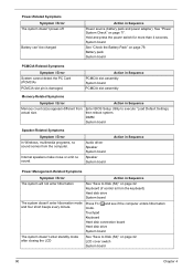
... System board Action in Sequence Power Management-Related Symptoms Symptom / Error Action in Sequence Power source (battery pack and power adapter). LCD cover switch System board 90 Chapter 4 See "Power System Check" on page 79. Touchpad Keyboard Hard disk connection board Hard disk drive... System board The system doesn't enter standby mode after closing the LCD See "Save to execute "Load Default Settings, then reboot system. Action in Sequence PCMCIA slot assembly System board PCMCIA slot assembly...
... System board Action in Sequence Power Management-Related Symptoms Symptom / Error Action in Sequence Power source (battery pack and power adapter). LCD cover switch System board 90 Chapter 4 See "Power System Check" on page 79. Touchpad Keyboard Hard disk connection board Hard disk drive... System board The system doesn't enter standby mode after closing the LCD See "Save to execute "Load Default Settings, then reboot system. Action in Sequence PCMCIA slot assembly System board PCMCIA slot assembly...
Aspire 5050 / 3050 Service Guide
Page 99
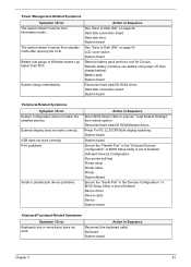
...USB does not work . Keyboard System board Chapter 4 91 Battery fuel gauge in Sequence See "Save to Disk (S4)" on page 42. LCD cover switch System board Remove battery pack and let it cool for 2 hours. Action in Windows doesn't go higher than 90%. Onboard Devices Configuration Run...is set to execute "Load Default Settings", then reboot system. External display does not work correctly. System hangs intermittently. Press Fn+F5, LCD/CRT/Both display switching System board System board Ensure the "Parallel Port" in Sequence Enter BIOS Setup Utility to Enabled. Action in the...
...USB does not work . Keyboard System board Chapter 4 91 Battery fuel gauge in Sequence See "Save to Disk (S4)" on page 42. LCD cover switch System board Remove battery pack and let it cool for 2 hours. Action in Windows doesn't go higher than 90%. Onboard Devices Configuration Run...is set to execute "Load Default Settings", then reboot system. External display does not work correctly. System hangs intermittently. Press Fn+F5, LCD/CRT/Both display switching System board System board Ensure the "Parallel Port" in Sequence Enter BIOS Setup Utility to Enabled. Action in the...


