
Aspire 2010/2020 Service Guide
Page 15
Aspire 2010 Front Panel # Icon Item Description 1 Headphone-in Jack Connects headphones for audio output. 2 Microphone-in Jack Connects an external microphone for audio input 3 4 in 1 Card Reader Supports: T Memory Stick T MultiMediaCard T SecureDigital T SmartMedia 4 Latch Locks and releases the lid 5 Bluetooth Button Starts Bluetooth functionality 6 Wireless Button Turns an internal wireless device on or off 8 Chapter 1
Aspire 2010 Front Panel # Icon Item Description 1 Headphone-in Jack Connects headphones for audio output. 2 Microphone-in Jack Connects an external microphone for audio input 3 4 in 1 Card Reader Supports: T Memory Stick T MultiMediaCard T SecureDigital T SmartMedia 4 Latch Locks and releases the lid 5 Bluetooth Button Starts Bluetooth functionality 6 Wireless Button Turns an internal wireless device on or off 8 Chapter 1

Aspire 2010/2020 Service Guide
Page 20
Aspire 2010 Bottom View # Item Description 1 Mini-PCI Slot Slot for adding mini-PCI cards 2 Hard Disk Bay Removable cover provides access to the computer's hard drive. 3 Memory Compartment Removable cover provides access to the memory slots for upgrading the computer's memory. 4 Battery Release Latch Unlatches the battery to remove the battery pack 5 Battery Pack The computer's removable battery Chapter 1 13
Aspire 2010 Bottom View # Item Description 1 Mini-PCI Slot Slot for adding mini-PCI cards 2 Hard Disk Bay Removable cover provides access to the computer's hard drive. 3 Memory Compartment Removable cover provides access to the memory slots for upgrading the computer's memory. 4 Battery Release Latch Unlatches the battery to remove the battery pack 5 Battery Pack The computer's removable battery Chapter 1 13

Aspire 2010/2020 Service Guide
Page 22
Aspire 2020 Front View # Icon Item Description 1 Headphone-in Jack Connects headphones for audio output 2 Microphone-in Jack Connects an external microphone for audio input 3 4 in 1 Card Reader Supports: T MemoryStick T MulitMediaCard T SecureDigital T SmartMedia 4 Latch Locks and release the lid 5 Bluetooth Button Enables Bluetooth functionality (manufacturing option) 6 Wireless Button Enables Wireless Connectivity (manufacturing option) Chapter 1 15
Aspire 2020 Front View # Icon Item Description 1 Headphone-in Jack Connects headphones for audio output 2 Microphone-in Jack Connects an external microphone for audio input 3 4 in 1 Card Reader Supports: T MemoryStick T MulitMediaCard T SecureDigital T SmartMedia 4 Latch Locks and release the lid 5 Bluetooth Button Enables Bluetooth functionality (manufacturing option) 6 Wireless Button Enables Wireless Connectivity (manufacturing option) Chapter 1 15

Aspire 2010/2020 Service Guide
Page 27
Aspire 2020 Bottom View # Item Description 1 Mini-PCI Slot Slot for adding mini-PCI slot 2 Hard Disk Bay Removable cover provides access to the computer's hard disk drive 3 Memory Compartment Removable cover provides access to the memory slots for upgrading the computer's memory 4 Battery Release Latch Unlatches the battery to remove the battery pack 5 Battery Pack The computer's removable battery 6 Sub-Woofer Outputs low/mid range audio 20 Chapter 1
Aspire 2020 Bottom View # Item Description 1 Mini-PCI Slot Slot for adding mini-PCI slot 2 Hard Disk Bay Removable cover provides access to the computer's hard disk drive 3 Memory Compartment Removable cover provides access to the memory slots for upgrading the computer's memory 4 Battery Release Latch Unlatches the battery to remove the battery pack 5 Battery Pack The computer's removable battery 6 Sub-Woofer Outputs low/mid range audio 20 Chapter 1

Aspire 2010/2020 Service Guide
Page 69
...base. 5. Disassemble the RAM and ODD 1. Remove the one screw to release the hard drive door.Then take it . 2. Aspire 2010/2020 Disassembly Procedure This section will guide you how to disassemble the system when you have turned off the system and all peripherals connected...to perform system service. Release the battery lock and slide the battery latch. 2. Disassemble the Battery and HDD 1. Then remove the battery pack. 3. Then take it away. 2. Disconnect the two wireless cables. 3. Chapter 3 Aspire 2010/2020 Remove the one screw to release the RAM board. 3. Press ...
...base. 5. Disassemble the RAM and ODD 1. Remove the one screw to release the hard drive door.Then take it . 2. Aspire 2010/2020 Disassembly Procedure This section will guide you how to disassemble the system when you have turned off the system and all peripherals connected...to perform system service. Release the battery lock and slide the battery latch. 2. Disassemble the Battery and HDD 1. Then remove the battery pack. 3. Then take it away. 2. Disconnect the two wireless cables. 3. Chapter 3 Aspire 2010/2020 Remove the one screw to release the RAM board. 3. Press ...
Aspire 2010/2020 Service Guide
Page 70
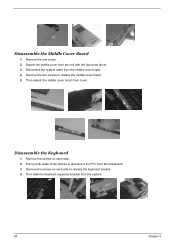
... middle cover board from the middle cover board. 4. Remove the two screws to disconnect the FFC from the mainboard. 3. Pull up both sides of the latches to release the middle cover board. 5. Disconnect the system cable from cover. Remove the screws on each side. 2. Then take the keyboard supporter bracket from...
... middle cover board from the middle cover board. 4. Remove the two screws to disconnect the FFC from the mainboard. 3. Pull up both sides of the latches to release the middle cover board. 5. Disconnect the system cable from cover. Remove the screws on each side. 2. Then take the keyboard supporter bracket from...

Aspire 2010/2020 Service Guide
Page 71
... the MDC cable before you take the MDC board. 3. Pull the entire LCD module from the mainboard. 5. Press down the both sides latches to release the LCD panel. 4. Chapter 3 Aspire 2010/2020 Disconnect the right and left speaker cables from the system. Remove the thirteen screws located on the base case. 2. Disassemble the...
... the MDC cable before you take the MDC board. 3. Pull the entire LCD module from the mainboard. 5. Press down the both sides latches to release the LCD panel. 4. Chapter 3 Aspire 2010/2020 Disconnect the right and left speaker cables from the system. Remove the thirteen screws located on the base case. 2. Disassemble the...

