Acer Aspire 1410, 1810T, and 1810TZ Service Guide
Page 8
...Camera Board 82 Removing the LCD Panel 83 Removing the LCD Brackets 85 Removing the FPC Cable 86 Removing the Antennas 87 LCD Reassembly Procedure 90 Replacing the Antennas 90 Replacing the FPC Cable 93 Replacing the LCD Brackets 94 Replacing the LCD Panel 95 Replacing the Camera Board ... BIOS Settings 134 LCD Failure 135 Built-In Keyboard Failure 136 TouchPad Failure 137 Internal Speaker Failure 138 Internal Microphone Failure 139 HDD Not Operating Correctly 140 USB Failure (Right up/down side 141 Other Failures 141 Intermittent Problems 142 Undetermined Problems 142 VIII
...Camera Board 82 Removing the LCD Panel 83 Removing the LCD Brackets 85 Removing the FPC Cable 86 Removing the Antennas 87 LCD Reassembly Procedure 90 Replacing the Antennas 90 Replacing the FPC Cable 93 Replacing the LCD Brackets 94 Replacing the LCD Panel 95 Replacing the Camera Board ... BIOS Settings 134 LCD Failure 135 Built-In Keyboard Failure 136 TouchPad Failure 137 Internal Speaker Failure 138 Internal Microphone Failure 139 HDD Not Operating Correctly 140 USB Failure (Right up/down side 141 Other Failures 141 Intermittent Problems 142 Undetermined Problems 142 VIII
Acer Aspire 1410, 1810T, and 1810TZ Service Guide
Page 54
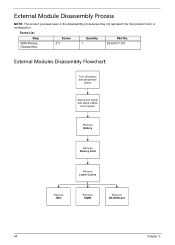
WAN Module 2*3 1 Disassembly 86.SA107.001 External Modules Disassembly Flowchart Turn off system and peripherals power Disconnect power and signal cables from system Remove Battery Remove Dummy Card Remove Lower Covers Remove HDD Remove DIMM Remove WLAN Board 44 Chapter 3 External Module Disassembly Process NOTE: The product previews seen in the disassembly procedures may not represent the final product color or configuration. Screw List Step Screw Quantity Part No.
WAN Module 2*3 1 Disassembly 86.SA107.001 External Modules Disassembly Flowchart Turn off system and peripherals power Disconnect power and signal cables from system Remove Battery Remove Dummy Card Remove Lower Covers Remove HDD Remove DIMM Remove WLAN Board 44 Chapter 3 External Module Disassembly Process NOTE: The product previews seen in the disassembly procedures may not represent the final product color or configuration. Screw List Step Screw Quantity Part No.

Acer Aspire 1410, 1810T, and 1810TZ Service Guide
Page 57
The actual model includes an FPC as pictured in the following images shows an FFC. Loosen the two captive screws. 3. Grasp the FPC cable and lift to remove. NOTE: The cable pictured in the image on page 45. 2. Lift the HDD cover up and away by the corner. 4. See "Removing the Battery Pack" on the right. 1. Chapter 3 47 Removing the Hard Disk Drive Module DISCLAIMER: The notebook sample in the following images may differ from the actual sample.
The actual model includes an FPC as pictured in the following images shows an FFC. Loosen the two captive screws. 3. Grasp the FPC cable and lift to remove. NOTE: The cable pictured in the image on page 45. 2. Lift the HDD cover up and away by the corner. 4. See "Removing the Battery Pack" on the right. 1. Chapter 3 47 Removing the Hard Disk Drive Module DISCLAIMER: The notebook sample in the following images may differ from the actual sample.

Acer Aspire 1410, 1810T, and 1810TZ Service Guide
Page 136
Connect the HDD FPC to the HDD. 2. The actual model includes an FPC as pictured in the following images shows an FFC. Lift up the clear plastic tab and place the HDD into its bay. 3. Connect the HDD FPC to the main board. Replacing the Hard Disk Drive DISCLAIMER: The notebook sample in the image on the right. 1. NOTE: The cable pictured in the above images may differ from the actual sample. 126 Chapter 3
Connect the HDD FPC to the HDD. 2. The actual model includes an FPC as pictured in the following images shows an FFC. Lift up the clear plastic tab and place the HDD into its bay. 3. Connect the HDD FPC to the main board. Replacing the Hard Disk Drive DISCLAIMER: The notebook sample in the image on the right. 1. NOTE: The cable pictured in the above images may differ from the actual sample. 126 Chapter 3

Acer Aspire 1410, 1810T, and 1810TZ Service Guide
Page 144
... to correct the problem. 1. If the BIOS settings are no red Xs or yellow exclamation marks. • There are still lost, replace the cables. 4. Reboot the computer. 2. See the User Manual for instructions on page 34. 3. Check the display resolution is not normal, right-click on...time to correct the problem. 1. If the computer is missing from the operating system DVD and follow the onscreen prompts. 11. If HDD information is experiencing HDD or ODD BIOS information loss, disconnect and reconnect the power and data cables between devices. Replace the Motherboard. 134 Chapter 4
... to correct the problem. 1. If the BIOS settings are no red Xs or yellow exclamation marks. • There are still lost, replace the cables. 4. Reboot the computer. 2. See the User Manual for instructions on page 34. 3. Check the display resolution is not normal, right-click on...time to correct the problem. 1. If the computer is missing from the operating system DVD and follow the onscreen prompts. 11. If HDD information is experiencing HDD or ODD BIOS information loss, disconnect and reconnect the power and data cables between devices. Replace the Motherboard. 134 Chapter 4

Acer Aspire 1410, 1810T, and 1810TZ Service Guide
Page 150
Disconnect all cables and jumpers on the Boot menu. 6. b. Select Repair your computer. For ... Click Next. NOTE: Click Load Drivers if controller drives are set as the first boot device on the HDD and ODD are required. Startup Repair attempts to the operating system DVD. For more information see Windows Help and...Startup Repair. Restart the computer and press F2 to complete the test. 8. Run the Windows Disk Defragmenter. Replace the HDD. See "Disassembly Process" on page 165. Run the Windows Vista Startup Repair Utility: a. When complete, click Finish....
Disconnect all cables and jumpers on the Boot menu. 6. b. Select Repair your computer. For ... Click Next. NOTE: Click Load Drivers if controller drives are set as the first boot device on the HDD and ODD are required. Startup Repair attempts to the operating system DVD. For more information see Windows Help and...Startup Repair. Restart the computer and press F2 to complete the test. 8. Run the Windows Disk Defragmenter. Replace the HDD. See "Disassembly Process" on page 165. Run the Windows Vista Startup Repair Utility: a. When complete, click Finish....
Acer Aspire 1410, 1810T, and 1810TZ Service Guide
Page 162
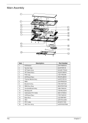
Main Assembly Item 1 2 3 4 5 6 7 8 9 10 11 12 13 14 15 16 17 18 Description K/B Module Top Sub Assy CRTCable Assy CRT Board Assy PCB Assy LED Board Assy Thermal Module Assy RAM Bluetooth Assy RAM Door Assy Touchpad Board Assy WirelessLAN Cardreader FFC Cable LAN Board Assy Base Assy HDD FPC Cable HDD Door Assy 152 18 Part Number 2ZH70KBR000 2IZH7TATN10 DDOZH7TH000 3SZH7CB0000 21ZH7PA0090 3RZH7LB0000 3AZH7TATN10 2ZH7RM02000 27ZH7BTTN00 3BZH7RDTN00 33ZH7TB0000 27ZHWL00040 DEFC0759004 3TZH7LB0000 2JZJ7BATN00 2ZH7HDC2000 50.SA107.006 3AZH7HDDTN00 Chapter 6
Main Assembly Item 1 2 3 4 5 6 7 8 9 10 11 12 13 14 15 16 17 18 Description K/B Module Top Sub Assy CRTCable Assy CRT Board Assy PCB Assy LED Board Assy Thermal Module Assy RAM Bluetooth Assy RAM Door Assy Touchpad Board Assy WirelessLAN Cardreader FFC Cable LAN Board Assy Base Assy HDD FPC Cable HDD Door Assy 152 18 Part Number 2ZH70KBR000 2IZH7TATN10 DDOZH7TH000 3SZH7CB0000 21ZH7PA0090 3RZH7LB0000 3AZH7TATN10 2ZH7RM02000 27ZH7BTTN00 3BZH7RDTN00 33ZH7TB0000 27ZHWL00040 DEFC0759004 3TZH7LB0000 2JZJ7BATN00 2ZH7HDC2000 50.SA107.006 3AZH7HDDTN00 Chapter 6

Acer Aspire 1410, 1810T, and 1810TZ Service Guide
Page 166
.../COVER/BRACKET ASSEMBLY UPPER CASE ASSY BLACK W/TP, FFC CABLE *2 UPPER CASE ASSY RED W/TP, FFC CABLE *2 UPPER CASE ASSY BLUE W/TP, FFC CABLE *2 60.SA207.001 60.SA307.001 60.SA107.001 LOWER CASE ASSY BLACK W/SPEAKER FOR HDMI 60.SA107.002 HDD COVER BLACK 42.SA107.001 RAM COVER BLACK 42.SA107....SA307.002 60.SA607.001 60.SA107.004 60.SA407.001 60.SA107.005 LCD BRACKET W/HINGE R 156 33.SA107.001 Chapter 6 CATEGORY PARTNAME LCD CABLE W/MIC FOR CCD ACER P/N 50.SA107.005 FPC...
.../COVER/BRACKET ASSEMBLY UPPER CASE ASSY BLACK W/TP, FFC CABLE *2 UPPER CASE ASSY RED W/TP, FFC CABLE *2 UPPER CASE ASSY BLUE W/TP, FFC CABLE *2 60.SA207.001 60.SA307.001 60.SA107.001 LOWER CASE ASSY BLACK W/SPEAKER FOR HDMI 60.SA107.002 HDD COVER BLACK 42.SA107.001 RAM COVER BLACK 42.SA107....SA307.002 60.SA607.001 60.SA107.004 60.SA407.001 60.SA107.005 LCD BRACKET W/HINGE R 156 33.SA107.001 Chapter 6 CATEGORY PARTNAME LCD CABLE W/MIC FOR CCD ACER P/N 50.SA107.005 FPC...


