Acer Aspire 1660 Service Guide
Page 7
... Introduction 1 Features 1 System Block Diagram 3 Board Layout 4 Top View 4 Bottom View 5 Panel 6 Front View 6 Left view 7 Right View 8 Rear Panel 9 Bottom View 10 Indicators 11 Keyboard 12 Special keys 12 Hot Keys 15 Hardware Specifications and Configurations 18 Chapter 2 System Utilities 32 BIOS Setup Utility 32 Navigating the BIOS Utility 33... LCD 58 Removing the LCD Brackets 59 Removing the LCD Coaxial Cable 59 Removing the LCD Hinges 60 Disassembling the Main Unit 61 Removing the Keyboard 61 Removing the RTC Battery 61 VII
... Introduction 1 Features 1 System Block Diagram 3 Board Layout 4 Top View 4 Bottom View 5 Panel 6 Front View 6 Left view 7 Right View 8 Rear Panel 9 Bottom View 10 Indicators 11 Keyboard 12 Special keys 12 Hot Keys 15 Hardware Specifications and Configurations 18 Chapter 2 System Utilities 32 BIOS Setup Utility 32 Navigating the BIOS Utility 33... LCD 58 Removing the LCD Brackets 59 Removing the LCD Coaxial Cable 59 Removing the LCD Hinges 60 Disassembling the Main Unit 61 Removing the Keyboard 61 Removing the RTC Battery 61 VII
Acer Aspire 1660 Service Guide
Page 8
... Wireless Unit 71 Chapter 4 Troubleshooting 72 System Check Procedures 73 External Diskette Drive Check 73 External CD-ROM Drive Check 73 Keyboard or Auxiliary Input Device Check 73 Memory check 74 Power System Check 74 Touchpad Check 76 Power-On Self-Test (POST)...Recovery 93 Chapter 5 Jumper and Connector Locations 98 Top View 98 Bottom View 99 Chapter 6 FRU (Field Replaceable Unit) List 100 Aspire 1660 Exploded Diagram 101 Appendix A Model Definition and Configuration 112 Model Name Definition 112 Appendix B Test Compatible Components 114 Microsoft Windows XP ...
... Wireless Unit 71 Chapter 4 Troubleshooting 72 System Check Procedures 73 External Diskette Drive Check 73 External CD-ROM Drive Check 73 Keyboard or Auxiliary Input Device Check 73 Memory check 74 Power System Check 74 Touchpad Check 76 Power-On Self-Test (POST)...Recovery 93 Chapter 5 Jumper and Connector Locations 98 Top View 98 Bottom View 99 Chapter 6 FRU (Field Replaceable Unit) List 100 Aspire 1660 Exploded Diagram 101 Appendix A Model Definition and Configuration 112 Model Name Definition 112 Appendix B Test Compatible Components 114 Microsoft Windows XP ...

Acer Aspire 1660 Service Guide
Page 11
Human-centric design T Rugged, yet extremely portable, construction T Stylish appearance T Full-size keyboard with four programmable launch keys T Comfortable palm rest area with well-positioned touchpad I/O Ports T T T T T T T T T T T T Two Type II or one Type III PC CardBus (PCMCIA) slot ...
Human-centric design T Rugged, yet extremely portable, construction T Stylish appearance T Full-size keyboard with four programmable launch keys T Comfortable palm rest area with well-positioned touchpad I/O Ports T T T T T T T T T T T T Two Type II or one Type III PC CardBus (PCMCIA) slot ...

Acer Aspire 1660 Service Guide
Page 13
Board Layout Top View 1 Line-in Port 2 Line-out Port 3 RJ45+RJ11 4 LCD Inverter Cable Connector 5 USB Port 6 USB Port 7 USB Port 8 USB Port 9 VGA Port 10 S-Video Port 11 LCD Coaxial Cable Connector 12 Parallel Port 13 DC-in Port 14 LCD Lid Switch 15 CPU Socket 16 North Bridge 17 Fan Connector 18 Second Fan Connector 19 Touchpad Cable Connector 20 HDD Connector 21 Keyboard Connector 22 Speaker Cable Connector 23 Optical Drive Connector 24 South Bridge 25 RTC Battery Connector 26 Launch Board Cable Connector 27 SW5 (Please see Chapter 5 for its settings) 28 PCMCIA Slot 4 Chapter 1
Board Layout Top View 1 Line-in Port 2 Line-out Port 3 RJ45+RJ11 4 LCD Inverter Cable Connector 5 USB Port 6 USB Port 7 USB Port 8 USB Port 9 VGA Port 10 S-Video Port 11 LCD Coaxial Cable Connector 12 Parallel Port 13 DC-in Port 14 LCD Lid Switch 15 CPU Socket 16 North Bridge 17 Fan Connector 18 Second Fan Connector 19 Touchpad Cable Connector 20 HDD Connector 21 Keyboard Connector 22 Speaker Cable Connector 23 Optical Drive Connector 24 South Bridge 25 RTC Battery Connector 26 Launch Board Cable Connector 27 SW5 (Please see Chapter 5 for its settings) 28 PCMCIA Slot 4 Chapter 1

Acer Aspire 1660 Service Guide
Page 15
... Display screen Status indicators Power button Launch Keys Palmrest Click buttons (left and right buttons function like a computer mouse. The left , center and right) Touchpad Keyboard Ventilation Slot Description Also called LCD (Liquid Crystal Display), displays computer output. Turns the computer on and off . Enables the computer to show the status...
... Display screen Status indicators Power button Launch Keys Palmrest Click buttons (left and right buttons function like a computer mouse. The left , center and right) Touchpad Keyboard Ventilation Slot Description Also called LCD (Liquid Crystal Display), displays computer output. Turns the computer on and off . Enables the computer to show the status...

Acer Aspire 1660 Service Guide
Page 21
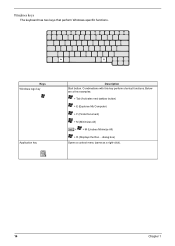
Special keys Lock keys The keyboard has three lock keys which you press the up or down arrow keys respectively. [ does not work with the arithmetic operators ), -, *, and /). Lock key Caps ... numeric data entry. The keys function as a calculator (complete with some applications. 12 Chapter 1 Use this mode when you need to connect an external keypad. Keyboard The keyboard has full-sized keys and an embedded keypad, separate cursor keys, two Windows keys and twelve function keys. When [ is in uppercase. When ] is...
Special keys Lock keys The keyboard has three lock keys which you press the up or down arrow keys respectively. [ does not work with the arithmetic operators ), -, *, and /). Lock key Caps ... numeric data entry. The keys function as a calculator (complete with some applications. 12 Chapter 1 Use this mode when you need to connect an external keypad. Keyboard The keyboard has full-sized keys and an embedded keypad, separate cursor keys, two Windows keys and twelve function keys. When [ is in uppercase. When ] is...

Acer Aspire 1660 Service Guide
Page 22
... in a normal manner. Hold Fn while typing letters on the keys. Desired access Number keys on embedded keypad Cursor-control keys on embedded keypad Main keyboard keys Num lock on the upper right corner of the keycaps. Hold Shift while using cursor-control keys. Chapter 1 13 keypad. Hold Fn while using...
... in a normal manner. Hold Fn while typing letters on the keys. Desired access Number keys on embedded keypad Cursor-control keys on embedded keypad Main keyboard keys Num lock on the upper right corner of the keycaps. Hold Shift while using cursor-control keys. Chapter 1 13 keypad. Hold Fn while using...
Acer Aspire 1660 Service Guide
Page 23
Keys Windows logo key Application key Description Start button. Combinations with this key perform shortcut functions. dialog box) Opens a context menu (same as a right-click). 14 Chapter 1 Below are a few examples: + Tab (Activates next taskbar button) + E (Explores My Computer) + F (Finds Document) + M (Minimizes All) j+ + M (Undoes Minimize All) + R (Displays the Run... Windows keys The keyboard has two keys that perform Windows-specific functions.
Keys Windows logo key Application key Description Start button. Combinations with this key perform shortcut functions. dialog box) Opens a context menu (same as a right-click). 14 Chapter 1 Below are a few examples: + Tab (Activates next taskbar button) + E (Explores My Computer) + F (Finds Document) + M (Minimizes All) j+ + M (Undoes Minimize All) + R (Displays the Run... Windows keys The keyboard has two keys that perform Windows-specific functions.

Acer Aspire 1660 Service Guide
Page 25
.... Click on the Language tab and click on Start, Control Panel. 2. The Euro symbol If your keyboard layout is set when you can type the Euro symbol on your keyboard. NOTE: for "En English (United States) is set to United States-International or United Kingdom or... if you have a keyboard with a European layout, you first set to United States-international. Verify that the keyboard layout used for US keyboard users: The keyboard layout is set up Windows. then select United States-International and click on OK...
.... Click on the Language tab and click on Start, Control Panel. 2. The Euro symbol If your keyboard layout is set when you can type the Euro symbol on your keyboard. NOTE: for "En English (United States) is set to United States-International or United Kingdom or... if you have a keyboard with a European layout, you first set to United States-international. Verify that the keyboard layout used for US keyboard users: The keyboard layout is set up Windows. then select United States-International and click on OK...

Acer Aspire 1660 Service Guide
Page 26
The Wireless and Bluetooth buttons cannot be set the other four launch keys, run the Acer Launch Manager. # 1 2 3 4 5 6 Icon Email Function Web browser P1 P2 Bluetooth (optional) Description Launches email application Launches Internet browser application User-programmable User-programmable Enables your ... button, Web browser button, P1, P2, Bluetooth and Wireless buttons. InviLink (optional) Enables your Bluetooth (manufacturing option). Launch Keys Located at the top of the keyboard are six buttons.
The Wireless and Bluetooth buttons cannot be set the other four launch keys, run the Acer Launch Manager. # 1 2 3 4 5 6 Icon Email Function Web browser P1 P2 Bluetooth (optional) Description Launches email application Launches Internet browser application User-programmable User-programmable Enables your ... button, Web browser button, P1, P2, Bluetooth and Wireless buttons. InviLink (optional) Enables your Bluetooth (manufacturing option). Launch Keys Located at the top of the keyboard are six buttons.
Acer Aspire 1660 Service Guide
Page 27
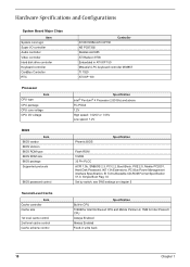
...Specifications and Configurations System Board Major Chips Item System core logic Super I/O controller Audio controller Video controller Hard disk drive controller Keyboard controller CardBus Controller RTC Processor CPU type Item CPU package CPU core voltage CPU I/O voltage BIOS Item BIOS vendor BIOS ... cache control Cache scheme control Controller ATI RC300M+ATI IXP150 NS PC87392 Realtek ALC655 ATI Radeon 9700 Embedded in ATI IXP 150 Mitsubish LPC keyboard controller M38857 TI 1520 ATI IXP 150 Specification Intel® Pentium® 4 Processor 2.80 Ghz and above FC-PGA2 1.2V High ...
...Specifications and Configurations System Board Major Chips Item System core logic Super I/O controller Audio controller Video controller Hard disk drive controller Keyboard controller CardBus Controller RTC Processor CPU type Item CPU package CPU core voltage CPU I/O voltage BIOS Item BIOS vendor BIOS ... cache control Cache scheme control Controller ATI RC300M+ATI IXP150 NS PC87392 Realtek ALC655 ATI Radeon 9700 Embedded in ATI IXP 150 Mitsubish LPC keyboard controller M38857 TI 1520 ATI IXP 150 Specification Intel® Pentium® 4 Processor 2.80 Ghz and above FC-PGA2 1.2V High ...
Acer Aspire 1660 Service Guide
Page 36
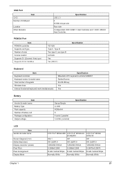
... Type II, Tpye III Two type II, one type III Left side Yes Yes (IRQ17) Specification Keyboard Item Keyboard controller Keyboard vendor & model name Total number of keypads Windows keys Internal & external keyboard work simultaneously Specification Mitsubishi LPC keyboard controller M38857 Darfon/Sunrex 84-/85-/88-key Yes Yes Battery Item Vendor & model name Battery...
... Type II, Tpye III Two type II, one type III Left side Yes Yes (IRQ17) Specification Keyboard Item Keyboard controller Keyboard vendor & model name Total number of keypads Windows keys Internal & external keyboard work simultaneously Specification Mitsubishi LPC keyboard controller M38857 Darfon/Sunrex 84-/85-/88-key Yes Yes Battery Item Vendor & model name Battery...
Acer Aspire 1660 Service Guide
Page 38
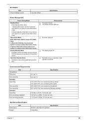
... Hibernation Mode Enter Hibernation Mode (suspend to HDD) when 1.Hibernation hot-key is pressed and system is ready to enter Hibernation mode. Display Standby Mode Keyboard, built-in standby mode. (spindle turned-off T Hard disk drive is ready to enter Hibernation mode 2.System Hibernation timer expires and system is in touchpad...
... Hibernation Mode Enter Hibernation Mode (suspend to HDD) when 1.Hibernation hot-key is pressed and system is ready to enter Hibernation mode. Display Standby Mode Keyboard, built-in standby mode. (spindle turned-off T Hard disk drive is ready to enter Hibernation mode 2.System Hibernation timer expires and system is in touchpad...

Acer Aspire 1660 Service Guide
Page 57
Start Battery HDD Module G*2 HDD HDD Holder *2 DIMM Cover Memory *2 Modem Cover Hinge Caps Wireless LAN Board D*2 Modem Board J*2 Middle Cover RTC Battery Keyboard F*6 LCD Module *2 Launch Board Second Fan J*3 Bracket Lower Case Assembly J*2 FDD Module J*5 F*10 D*4 Upper Case Assembly D*4 Wireless LAN Antenna Touchpad Cover J*3 ...flowchart on the succeeding page gives you a graphic representation on the entire disassembly sequence and instructs you must first remove the keyboard, then disassemble the inside assembly frame in that need to be removed during servicing.
Start Battery HDD Module G*2 HDD HDD Holder *2 DIMM Cover Memory *2 Modem Cover Hinge Caps Wireless LAN Board D*2 Modem Board J*2 Middle Cover RTC Battery Keyboard F*6 LCD Module *2 Launch Board Second Fan J*3 Bracket Lower Case Assembly J*2 FDD Module J*5 F*10 D*4 Upper Case Assembly D*4 Wireless LAN Antenna Touchpad Cover J*3 ...flowchart on the succeeding page gives you a graphic representation on the entire disassembly sequence and instructs you must first remove the keyboard, then disassemble the inside assembly frame in that need to be removed during servicing.

Acer Aspire 1660 Service Guide
Page 70
Use a plastic tweezers or a plastic flat screwdriver to disconnect the keyboard cable from the main board carefully, then remove the keyboard. See "Removing the Battery" on page 54. 3. Removing the Fan 1. Disconnect the fan cable and remove the three screws fastening the fan.... Removing the RTC Battery 1. Then remove the fan. 61 Chapter 3 To remove the keyboard, carefully pull the keyboard out and upwards as the pticute shows. 4. See "Removing the Middle Cover" on page 50. 2. See "Removing the Battery" on page 50...
Use a plastic tweezers or a plastic flat screwdriver to disconnect the keyboard cable from the main board carefully, then remove the keyboard. See "Removing the Battery" on page 54. 3. Removing the Fan 1. Disconnect the fan cable and remove the three screws fastening the fan.... Removing the RTC Battery 1. Then remove the fan. 61 Chapter 3 To remove the keyboard, carefully pull the keyboard out and upwards as the pticute shows. 4. See "Removing the Middle Cover" on page 50. 2. See "Removing the Battery" on page 50...

Acer Aspire 1660 Service Guide
Page 71
... "Removing the Middle Cover" on page 61. 5. See "Removing the Battery" on page 62. 7. See "Removing the Thermal Module" on page 50. 2. See "Removing the Keyboard" on page 54. 3. See "Removing the Middle Cover" on page 61. 4. Lift up the CPU socket lever. Then remove the CPU. See "Removing the Battery..." on page 61. 4. Chapter 3 62 Remember to press down the lever as the video shows after you remove the CPU. See "Removing the Keyboard" on page 50. 2. See "Removing the Fan" on page 61. 5. See "Removing the Fan" on page 61. 6.
... "Removing the Middle Cover" on page 61. 5. See "Removing the Battery" on page 62. 7. See "Removing the Thermal Module" on page 50. 2. See "Removing the Keyboard" on page 54. 3. See "Removing the Middle Cover" on page 61. 4. Lift up the CPU socket lever. Then remove the CPU. See "Removing the Battery..." on page 61. 4. Chapter 3 62 Remember to press down the lever as the video shows after you remove the CPU. See "Removing the Keyboard" on page 50. 2. See "Removing the Fan" on page 61. 5. See "Removing the Fan" on page 61. 6.

Acer Aspire 1660 Service Guide
Page 72
See "Removing the RTC Battery" on page 61. 2. See "Removing the Keyboard" on page 61. 5. Installing the Processor 1. Lift up the CPU lever, then place the CPU back to the lower case. Remove the 5 screws that secure ... case to the socket. See "Removing the Battery" on page 61. 6. Disconnect the touchpad cable. 3. See "Removing the Fan" on page 50. 2. See "Removing the Keyboard" on page 61. 4.
See "Removing the RTC Battery" on page 61. 2. See "Removing the Keyboard" on page 61. 5. Installing the Processor 1. Lift up the CPU lever, then place the CPU back to the lower case. Remove the 5 screws that secure ... case to the socket. See "Removing the Battery" on page 61. 6. Disconnect the touchpad cable. 3. See "Removing the Fan" on page 50. 2. See "Removing the Keyboard" on page 61. 4.

Acer Aspire 1660 Service Guide
Page 73
See "Removing the Upper Case Assemly" on page 61. 4. Chapter 3 64 See "Removing the Keyboard" on page 63. 5. To detach the touch pad board, first disconnect the touch pad cable from the upper case. Removing the Touchpad Cable 1. Removing the ...
See "Removing the Upper Case Assemly" on page 61. 4. Chapter 3 64 See "Removing the Keyboard" on page 63. 5. To detach the touch pad board, first disconnect the touch pad cable from the upper case. Removing the Touchpad Cable 1. Removing the ...

Acer Aspire 1660 Service Guide
Page 74
...Fan" on page 61. 5. See "Removing the Thermal Module" on page 50. 2. See "Removing the Battery" on page 62. 6. See "Removing the Keyboard" on page 50. 2. See "Removing the Battery" on page 61. 4. Remove the screw that fastens the CPU heatsink plate then remove it . Remove the ...touchpad scroll key then remove the touchpad cable. See "Removing the Keyboard" on page 61. 5. Remove the seven screws holding the VGA thermal plate then remove it . 65 Chapter 3 See "Removing the Fan" on page...
...Fan" on page 61. 5. See "Removing the Thermal Module" on page 50. 2. See "Removing the Battery" on page 62. 6. See "Removing the Keyboard" on page 50. 2. See "Removing the Battery" on page 61. 4. Remove the screw that fastens the CPU heatsink plate then remove it . Remove the ...touchpad scroll key then remove the touchpad cable. See "Removing the Keyboard" on page 61. 5. Remove the seven screws holding the VGA thermal plate then remove it . 65 Chapter 3 See "Removing the Fan" on page...

Acer Aspire 1660 Service Guide
Page 75
... the steps above. See "Removing the RTC Battery" on page 61. 6. See "Removing the Battery" on page 61. 4. Removing the ODD Module(2) 1. See "Removing the Keyboard" on page 50. 2. Chapter 3 66 See "Removing the Battery" on page 55. 4. See "Removing the LCD Module" on page 50. 2. Remove the three screws that...
... the steps above. See "Removing the RTC Battery" on page 61. 6. See "Removing the Battery" on page 61. 4. Removing the ODD Module(2) 1. See "Removing the Keyboard" on page 50. 2. Chapter 3 66 See "Removing the Battery" on page 55. 4. See "Removing the LCD Module" on page 50. 2. Remove the three screws that...


