

aa500ug.pdf
Page 9
... Front Panel Connectors 1-7 1.5 Installing Components 1-8 1.5.1 ESD Precautions 1-9 1.5.2 Pre-installation Instructions 1-9 1.5.3 Post-installation Instructions 1-10 1.6 Installing and Removing a Heatsink 1-11 1.7 Installing a Pentium III Processor 1-13 1.8 Removing a Pentium III Processor 1-15 1.9 Memory Upgrade 1-16 1.9.1 Memory Configurations 1-16 1.9.2 Installing a DIMM 1-17 1.9.3 Removing a DIMM 1-18 1.9.4 Reconfiguring the System 1-19 1.10 Server Management Features 1-20 1.10.1 Advanced Server Manager (ASM Pro 1-20 1.11 Error Messages 1-20 1.11.1 Software Error Messages...
... Front Panel Connectors 1-7 1.5 Installing Components 1-8 1.5.1 ESD Precautions 1-9 1.5.2 Pre-installation Instructions 1-9 1.5.3 Post-installation Instructions 1-10 1.6 Installing and Removing a Heatsink 1-11 1.7 Installing a Pentium III Processor 1-13 1.8 Removing a Pentium III Processor 1-15 1.9 Memory Upgrade 1-16 1.9.1 Memory Configurations 1-16 1.9.2 Installing a DIMM 1-17 1.9.3 Removing a DIMM 1-18 1.9.4 Reconfiguring the System 1-19 1.10 Server Management Features 1-20 1.10.1 Advanced Server Manager (ASM Pro 1-20 1.11 Error Messages 1-20 1.11.1 Software Error Messages...

aa500ug.pdf
Page 13
...AHA-3950U2B 3-7 3-5 SCSI Parity Checking Selection 3-8 3-6 Host Adapter SCSI Termination Selection for AHA-3950U2B 3-9 3-7 Boot Device Options Screen 3-10 3-8 SCSI Device Configuration Screen for AHA-3950U2B 3-11 3-9 Advanced Configuration Options Screen 3-16 3-10 SCSI Disk Utilities Screen for AHA-3950U2B 3-19 List of Tables 1-1 Jumper Settings 1-5 1-2 Connector Functions 1-5 1-3 Memory Configurations 1-16 1-4 System Error Messages 1-22 2-1 Parallel Port Operation Mode Settings 2-18 2-2 Drive Control Settings 2-40 3-1 Default Settings for SCSI Controller and All Devices 3-2 xiii
...AHA-3950U2B 3-7 3-5 SCSI Parity Checking Selection 3-8 3-6 Host Adapter SCSI Termination Selection for AHA-3950U2B 3-9 3-7 Boot Device Options Screen 3-10 3-8 SCSI Device Configuration Screen for AHA-3950U2B 3-11 3-9 Advanced Configuration Options Screen 3-16 3-10 SCSI Disk Utilities Screen for AHA-3950U2B 3-19 List of Tables 1-1 Jumper Settings 1-5 1-2 Connector Functions 1-5 1-3 Memory Configurations 1-16 1-4 System Error Messages 1-22 2-1 Parallel Port Operation Mode Settings 2-18 2-2 Drive Control Settings 2-40 3-1 Default Settings for SCSI Controller and All Devices 3-2 xiii

aa500ug.pdf
Page 23
... strap is not available, maintain contact with the system chassis throughout any expansion boards or peripherals that block access to install it. 2. Open the system according to install. System Board 1-9 Do not attempt the procedures described in section 1.5.1 before you install a system component: 1. 1.5.1 ESD Precautions Electrostatic discharge (ESD) can damage your processor, disk drives, expansion boards, and other components. See the following precautions before...
... strap is not available, maintain contact with the system chassis throughout any expansion boards or peripherals that block access to install it. 2. Open the system according to install. System Board 1-9 Do not attempt the procedures described in section 1.5.1 before you install a system component: 1. 1.5.1 ESD Precautions Electrostatic discharge (ESD) can damage your processor, disk drives, expansion boards, and other components. See the following precautions before...
aa500ug.pdf
Page 36
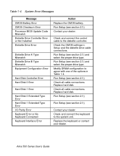
...Check all cable connections. Modify DRAM configuration to agree with one of the options in Setup and the diskette drive cable connections. Replace the keyboard or contact your dealer. Table 1-4 System Error Messages Message CMOS Battery Error CMOS Checksum Error Processor BIOS Update Code Mismatch Diskette Drive Controller Error or Not Installed Diskette Drive Error Diskette Drive A Type Mismatch Diskette Drive B Type Mismatch Equipment Configuration Error Hard Disk Controller Error Hard Disk 0 Error Hard Disk 1 Error Hard Disk 0 Extended Type Error Hard Disk 1 Extended Type Error...
...Check all cable connections. Modify DRAM configuration to agree with one of the options in Setup and the diskette drive cable connections. Replace the keyboard or contact your dealer. Table 1-4 System Error Messages Message CMOS Battery Error CMOS Checksum Error Processor BIOS Update Code Mismatch Diskette Drive Controller Error or Not Installed Diskette Drive Error Diskette Drive A Type Mismatch Diskette Drive B Type Mismatch Equipment Configuration Error Hard Disk Controller Error Hard Disk 0 Error Hard Disk 1 Error Hard Disk 0 Extended Type Error Hard Disk 1 Extended Type Error...
aa500ug.pdf
Page 38
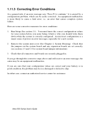
... by a configuration problem, which is a major cause of power-on the system board and any expansion boards are some corrective measures for error conditions: 1. Altos 500 Series User's Guide Check that causes complete system failure. Remove the system unit cover (See Chapter 4, System Housing). In either case, contact an authorized service center for your configuration values are securely plugged in a damaged or defective chip. Here are set correctly...
... by a configuration problem, which is a major cause of power-on the system board and any expansion boards are some corrective measures for error conditions: 1. Altos 500 Series User's Guide Check that causes complete system failure. Remove the system unit cover (See Chapter 4, System Housing). In either case, contact an authorized service center for your configuration values are securely plugged in a damaged or defective chip. Here are set correctly...

aa500ug.pdf
Page 48
Altos 500 Series User's Guide Possible settings for the Floppy Drive parameters are: • [ None ] • [360 KB, 5.25-inch] • [1.2 MB, 5.25-inch] • [720 KB, 3.5-inch] • [1.44 MB, 3.5-inch] • [2.88 MB, 3.5-inch] Follow the same procedure to view the options ...and select the appropriate value. Choose None if you do not have a second floppy drive. Press or key to configure floppy drive B. The following screen shows the Disk Drives menu screen: Disk Drives Diskette Drive A xx-MB, xx-inch] Diskette Drive B None ] LS-120 Drive as ...
Altos 500 Series User's Guide Possible settings for the Floppy Drive parameters are: • [ None ] • [360 KB, 5.25-inch] • [1.2 MB, 5.25-inch] • [720 KB, 3.5-inch] • [1.44 MB, 3.5-inch] • [2.88 MB, 3.5-inch] Follow the same procedure to view the options ...and select the appropriate value. Choose None if you do not have a second floppy drive. Press or key to configure floppy drive B. The following screen shows the Disk Drives menu screen: Disk Drives Diskette Drive A xx-MB, xx-inch] Diskette Drive B None ] LS-120 Drive as ...
aa500ug.pdf
Page 52
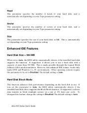
... setting. Other operating systems require this parameter to be set to Auto, the BIOS utility automatically detects if the installed hard disk drive supports the Block Mode function. Hard Disk Block Mode This function enhances disk performance depending on your Type parameter setting. To disregard the feature, change the setting to Disabled. Altos 500 Series User's Guide Sector This parameter specifies the number of sectors of your hard disk, and is automatically set depending on your Type parameter setting. Enhanced IDE Features Hard Disk...
... setting. Other operating systems require this parameter to be set to Auto, the BIOS utility automatically detects if the installed hard disk drive supports the Block Mode function. Hard Disk Block Mode This function enhances disk performance depending on your Type parameter setting. To disregard the feature, change the setting to Disabled. Altos 500 Series User's Guide Sector This parameter specifies the number of sectors of your hard disk, and is automatically set depending on your Type parameter setting. Enhanced IDE Features Hard Disk...
aa500ug.pdf
Page 70
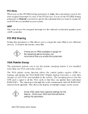
... you set the PCI IRQ Setting parameter to Auto, these parameters specify the auto-assigned interrupt for the onboard accelerated graphics port (AGP) controller. Altos 500 Series User's Guide VGA Palette Snoop This parameter permits you to use the palette snooping feature if you installed more than one VGA card in your VGA card manual before setting this feature. Some VGA cards have required settings for the remaining device...
... you set the PCI IRQ Setting parameter to Auto, these parameters specify the auto-assigned interrupt for the onboard accelerated graphics port (AGP) controller. Altos 500 Series User's Guide VGA Palette Snoop This parameter permits you to use the palette snooping feature if you installed more than one VGA card in your VGA card manual before setting this feature. Some VGA cards have required settings for the remaining device...

aa500ug.pdf
Page 97
... a SCSI hard disk drive connected to Disabled. If you to control which removable-media drives are supported by the SCSI controller BIOS, do not remove the media while the drive is enabled. All removable-media drives supported by the BIOS. No removable-media drives are treated as hard disk drives. In this option to the SCSI controller. it were a hard disk drive; The SCSI controller BIOS must be enabled if you can remove the disk media during operation. Default is Boot Only. If a removable-media SCSI device is enabled. SCSISelect Configuration Utility 3-17...
... a SCSI hard disk drive connected to Disabled. If you to control which removable-media drives are supported by the SCSI controller BIOS, do not remove the media while the drive is enabled. All removable-media drives supported by the BIOS. No removable-media drives are treated as hard disk drives. In this option to the SCSI controller. it were a hard disk drive; The SCSI controller BIOS must be enabled if you can remove the disk media during operation. Default is Boot Only. If a removable-media SCSI device is enabled. SCSISelect Configuration Utility 3-17...

aa500ug.pdf
Page 100
... the Verify Disk Media utility. Use SCSI Disk Utilities to display the firmware version. Use the arrow keys to highlight a disk device, then press Enter to check the hard disk drive firmware version. Verify Disk Media The Verify Disk Media utility scans the selected device's media for defects. Format Disk The Format Disk utility performs a low-level format on the drive. You cannot abort a low-level format once it is compatible with a non-Adaptec SCSI controller. Altos 500 Series User's Guide Run it prompts...
... the Verify Disk Media utility. Use SCSI Disk Utilities to display the firmware version. Use the arrow keys to highlight a disk device, then press Enter to check the hard disk drive firmware version. Verify Disk Media The Verify Disk Media utility scans the selected device's media for defects. Format Disk The Format Disk utility performs a low-level format on the drive. You cannot abort a low-level format once it is compatible with a non-Adaptec SCSI controller. Altos 500 Series User's Guide Run it prompts...
aa500ug.pdf
Page 105
... disk drive" means a disk drive attached to the device. Chapter 3 - Start unit request failed The BIOS was unable to send a Start Unit Command to the computer through the Setup program. Time-out failure during SCSI Test Unit Ready command! If the computer successfully restarts, check SCSI bus termination and cable connections. Standard hard disk drives can be defective. SCSISelect Configuration Utility 3-25 or Time-out failure during SCSI Inquiry command! Check SCSI bus termination. SCSI drives are installed, then the non-SCSI disk drive is always the boot device...
... disk drive" means a disk drive attached to the device. Chapter 3 - Start unit request failed The BIOS was unable to send a Start Unit Command to the computer through the Setup program. Time-out failure during SCSI Test Unit Ready command! If the computer successfully restarts, check SCSI bus termination and cable connections. Standard hard disk drives can be defective. SCSISelect Configuration Utility 3-25 or Time-out failure during SCSI Inquiry command! Check SCSI bus termination. SCSI drives are installed, then the non-SCSI disk drive is always the boot device...
aa500ug.pdf
Page 106
... standard hard disk (if one exists) out of devices on the SCSI bus. Check the drive installation manual for information about setting the SCSI ID for that there are no SCSI ID conflicts. Using a Standard Drive as C and a SCSI Drive as D • Use the Setup program to SCSI ID 0 and that device. You can also use the SCSISelect utility to determine the SCSI IDs of the configuration. • Disable Onboard SCSI Boot in a Setup program, or on setting the SCSI...
... standard hard disk (if one exists) out of devices on the SCSI bus. Check the drive installation manual for information about setting the SCSI ID for that there are no SCSI ID conflicts. Using a Standard Drive as C and a SCSI Drive as D • Use the Setup program to SCSI ID 0 and that device. You can also use the SCSISelect utility to determine the SCSI IDs of the configuration. • Disable Onboard SCSI Boot in a Setup program, or on setting the SCSI...
aa500ug.pdf
Page 107
... SCSI addresses of the SCSISelect utility. Check the drive manual for information on setting the SCSI ID for that device. • Try enabling Include in BIOS Scan in a Setup program, or on a SCSI device. Using a SCSI Drive as C and Another SCSI Drive as D • Be sure that the SCSI drive to be used as drive D to SCSI ID 0. • Be sure that SCSI parity checking is consistently enabled or disabled on all devices on the SCSI bus. • Verify that the SCSI controllers...
... SCSI addresses of the SCSISelect utility. Check the drive manual for information on setting the SCSI ID for that device. • Try enabling Include in BIOS Scan in a Setup program, or on a SCSI device. Using a SCSI Drive as C and Another SCSI Drive as D • Be sure that the SCSI drive to be used as drive D to SCSI ID 0. • Be sure that SCSI parity checking is consistently enabled or disabled on all devices on the SCSI bus. • Verify that the SCSI controllers...

aa500ug.pdf
Page 123
... adapter settings, 3-5 Default values, 3-1 Device connected, but not ready, 3- 24 Multiple controllers, configuring, 3-21 Options, 3-4 Overview, 3-1 Running, 3-3 Running the utility, 3-3 SCSI disk utilities, 3-19 Troubleshooting checklist, 3-22 When to use, 3-3 SCSISelect utility options, 3-4 Configure/view host adapter settings menu, 3-5 SCSI disk utilities, 3-19 Serial port 1, 2-7 Serial port 2, 2-7 Serial ports 1 and 2, 2-16 Server management features, 1-20 Advanced, 1-20 Setup password, 2-35, 2-37, 2-38 bypassing, 2-38 changing, 2-37 removing, 2-37 Silent boot, 2-24 Software error messages...
... adapter settings, 3-5 Default values, 3-1 Device connected, but not ready, 3- 24 Multiple controllers, configuring, 3-21 Options, 3-4 Overview, 3-1 Running, 3-3 Running the utility, 3-3 SCSI disk utilities, 3-19 Troubleshooting checklist, 3-22 When to use, 3-3 SCSISelect utility options, 3-4 Configure/view host adapter settings menu, 3-5 SCSI disk utilities, 3-19 Serial port 1, 2-7 Serial port 2, 2-7 Serial ports 1 and 2, 2-16 Server management features, 1-20 Advanced, 1-20 Setup password, 2-35, 2-37, 2-38 bypassing, 2-38 changing, 2-37 removing, 2-37 Silent boot, 2-24 Software error messages...

aa500ug.pdf
Page 124
... 2-12 Altos 500 Series User's Guide Internal cache, 2-5, 2-29 Parallel port, 2-7, 2-17 Processor, 2-5, 2-34 Processor speed, 2-5, 2-34 PS/2 mouse, 2-7, 2-19 Serial port 1, 2-7 Serial port 2, 2-7 Total memory, 2-7 System S/N, 2-8 System security, 2-35 Disk drive control, 2-40 Power-on password, 2-39 Setup password, 2-35, 2-37, 2-38 System utilities BIOS startup messages, 3-23 Configuring multiple SCSI controllers, 3-21 SCSI troubleshooting checklist, 3- 22 SCSISelect configuration, 3-1 SCSISelect utility options, 3-4 System wake-up event, 2-22 T Time, 2-27 Total memory, 2-7 W When to use the...
... 2-12 Altos 500 Series User's Guide Internal cache, 2-5, 2-29 Parallel port, 2-7, 2-17 Processor, 2-5, 2-34 Processor speed, 2-5, 2-34 PS/2 mouse, 2-7, 2-19 Serial port 1, 2-7 Serial port 2, 2-7 Total memory, 2-7 System S/N, 2-8 System security, 2-35 Disk drive control, 2-40 Power-on password, 2-39 Setup password, 2-35, 2-37, 2-38 System utilities BIOS startup messages, 3-23 Configuring multiple SCSI controllers, 3-21 SCSI troubleshooting checklist, 3- 22 SCSISelect configuration, 3-1 SCSISelect utility options, 3-4 System wake-up event, 2-22 T Time, 2-27 Total memory, 2-7 W When to use the...
Altos 500 Service Guide
Page 53
...boot the operating system or when you receive this type normally appears during the power-on self-test, before the operating system prompt appears. Message CMOS Battery Error CMOS Checksum Error CPU BIOS Update Code Mismatch Diskette Drive Controller Error or Not Installed Diskette Drive Error Diskette Drive A Type Mismatch Diskette Drive B Type Mismatch Equipment Configuration Error Hard Disk Controller Error Action Replace the battery or contact your application. Check the CMOS settings in chapter 2, Memory Configurations. BIOS Utility 2-21 Check and connect the control cable...
...boot the operating system or when you receive this type normally appears during the power-on self-test, before the operating system prompt appears. Message CMOS Battery Error CMOS Checksum Error CPU BIOS Update Code Mismatch Diskette Drive Controller Error or Not Installed Diskette Drive Error Diskette Drive A Type Mismatch Diskette Drive B Type Mismatch Equipment Configuration Error Hard Disk Controller Error Action Replace the battery or contact your application. Check the CMOS settings in chapter 2, Memory Configurations. BIOS Utility 2-21 Check and connect the control cable...
Altos 500 Service Guide
Page 70
...-bit Access Enabling this parameter to Disabled. To disregard the feature, change the setting to Auto, the BIOS utility automatically detects if the installed hard disk drive supports the Block Mode function. If your hard disk. Hard Disk Block Mode This function enhances disk performance depending on the hard disk in better hard disk performance. Advanced PIO Mode When set this parameter improves system performance by increasing the transfer rate. By setting this parameter to Disabled. CD-ROM Drive DMA Mode 3-14 Altos 500...
...-bit Access Enabling this parameter to Disabled. To disregard the feature, change the setting to Auto, the BIOS utility automatically detects if the installed hard disk drive supports the Block Mode function. If your hard disk. Hard Disk Block Mode This function enhances disk performance depending on the hard disk in better hard disk performance. Advanced PIO Mode When set this parameter improves system performance by increasing the transfer rate. By setting this parameter to Disabled. CD-ROM Drive DMA Mode 3-14 Altos 500...
Altos 500 Service Guide
Page 80
... information. Please refer to your desktop system. The configuration table gives a summary of the configuration table after POST but before booting. Memory Test When set to Disabled, the system detects only the memory size and bypasses the test routine. When set to Enabled, this parameter allows the system to enable or disable the appearance of the hardware devices and settings that intervenes in the Boot Sequence parameter. 3-24 Altos 500 System Guide
... information. Please refer to your desktop system. The configuration table gives a summary of the configuration table after POST but before booting. Memory Test When set to Disabled, the system detects only the memory size and bypasses the test routine. When set to Enabled, this parameter allows the system to enable or disable the appearance of the hardware devices and settings that intervenes in the Boot Sequence parameter. 3-24 Altos 500 System Guide
Altos 500 Service Guide
Page 93
... your computer's housing and reboot your setup password, you can either change the existing Setup password or remove it whenever you to type it by hardware. Turn off and unplug the computer. 2. See chapter 2 for the location of JP3. 3. Once you set this password, enter the Setup Utility, select System Security, and then highlight the Power-on Password secures your system against unauthorized use. Open the computer housing and...
... your computer's housing and reboot your setup password, you can either change the existing Setup password or remove it whenever you to type it by hardware. Turn off and unplug the computer. 2. See chapter 2 for the location of JP3. 3. Once you set this password, enter the Setup Utility, select System Security, and then highlight the Power-on Password secures your system against unauthorized use. Open the computer housing and...

Altos 500 Service Guide
Page 100
Jumper Settings Jumper ROM Remapping JP1 VGA Feature JP2 VGA Controller JP3 Interrupt JP4 Setting 1-2 2-3* 1-2 2-3* 1-2 2-3* 1-2 2-3* Function Map top 8K to bottom 8K No remapping Disabled Enabled Disabled Enabled Enabled Disabled Connector Functions Connector CN1 CN2 CN3 CN4 CN5 CN6 Function 68-pin Wide SCSI connector 50-pin Fast SCSI-II connector ATI Multimedia connector Ultra SCSI connector LED connector VGA connector Card Installation Follow these steps to install the SCSI/VGA combo card. 1. Remove a bracket cover opposite an empty PCI slot. * Default setting 4-2 Altos 500 System ...
Jumper Settings Jumper ROM Remapping JP1 VGA Feature JP2 VGA Controller JP3 Interrupt JP4 Setting 1-2 2-3* 1-2 2-3* 1-2 2-3* 1-2 2-3* Function Map top 8K to bottom 8K No remapping Disabled Enabled Disabled Enabled Enabled Disabled Connector Functions Connector CN1 CN2 CN3 CN4 CN5 CN6 Function 68-pin Wide SCSI connector 50-pin Fast SCSI-II connector ATI Multimedia connector Ultra SCSI connector LED connector VGA connector Card Installation Follow these steps to install the SCSI/VGA combo card. 1. Remove a bracket cover opposite an empty PCI slot. * Default setting 4-2 Altos 500 System ...


