Acer Aspire One D270 Service Guide
Page 4
...change is made, it may not be provided by the regional Acer office to the basic configuration for repair and service of a machine (such as add-on the Website. Acer-authorized Service Providers: The Acer office may have a different part number code than those given ...responsible personnel/channel to -date information available on cards, modems, or extra memory capabilities). iv General Information 0 This service guide provides all technical information relating to order FRU parts for Acer's global product offering. To better fit local market requirements and enhance product ...
...change is made, it may not be provided by the regional Acer office to the basic configuration for repair and service of a machine (such as add-on the Website. Acer-authorized Service Providers: The Acer office may have a different part number code than those given ...responsible personnel/channel to -date information available on cards, modems, or extra memory capabilities). iv General Information 0 This service guide provides all technical information relating to order FRU parts for Acer's global product offering. To better fit local market requirements and enhance product ...
Acer Aspire One D270 Service Guide
Page 5
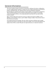
CHAPTER 1 Hardware Specifications Features 1-5 Operating System 1-5 Platform 1-5 System Memory 1-5 Display 1-5 Audio Subsystem 1-5 Graphics 1-6 Storage Subsystem 1-6 Privacy Control 1-6 Webcam 1-6 Wireless and networking 1-7 Dimension and Weight 1-7 Color options 1-7 Power Adapter and Battery 1-7 Input and ... 1-24 System Board Major Chips 1-25 Processor 1-25 Processor Specifications 1-25 CPU Fan True Value Table (AC/DC Mode 1-26 System Memory 1-26 Memory Combinations 1-26 Video Interface 1-27 BIOS 1-27 Keyboard 1-27 Hard Disk Drive (AVL components 1-28 LCD 10.1 1-29 v
CHAPTER 1 Hardware Specifications Features 1-5 Operating System 1-5 Platform 1-5 System Memory 1-5 Display 1-5 Audio Subsystem 1-5 Graphics 1-6 Storage Subsystem 1-6 Privacy Control 1-6 Webcam 1-6 Wireless and networking 1-7 Dimension and Weight 1-7 Color options 1-7 Power Adapter and Battery 1-7 Input and ... 1-24 System Board Major Chips 1-25 Processor 1-25 Processor Specifications 1-25 CPU Fan True Value Table (AC/DC Mode 1-26 System Memory 1-26 Memory Combinations 1-26 Video Interface 1-27 BIOS 1-27 Keyboard 1-27 Hard Disk Drive (AVL components 1-28 LCD 10.1 1-29 v
Acer Aspire One D270 Service Guide
Page 7
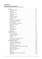
... 3-16 3G Module Removal 3-17 3G Module Installation 3-17 WLAN (Wireless Local Area Network) Module Removal . . . 3-18 WLAN Module Installation 3-18 DIMM (Dual In-line Memory Module) Removal 3-19 DIMM Installation 3-19 Upper Case Removal 3-20 Upper Case Installation 3-21 Bluetooth Module Removal 3-22 Bluetooth Module Installation 3-22 Mainboard Removal 3-23...
... 3-16 3G Module Removal 3-17 3G Module Installation 3-17 WLAN (Wireless Local Area Network) Module Removal . . . 3-18 WLAN Module Installation 3-18 DIMM (Dual In-line Memory Module) Removal 3-19 DIMM Installation 3-19 Upper Case Removal 3-20 Upper Case Installation 3-21 Bluetooth Module Removal 3-22 Bluetooth Module Installation 3-22 Mainboard Removal 3-23...

Acer Aspire One D270 Service Guide
Page 12
Features 1-5 Operating System 1-5 Platform 1-5 System Memory 1-5 Display 1-5 Audio Subsystem 1-5 Graphics 1-6 Storage Subsystem 1-6 Privacy Control 1-6 Webcam 1-6 Wireless and networking 1-7 Dimension and Weight 1-7 Color options 1-7 Power Adapter and Battery 1-7 ...Computer specifications 1-24 System Board Major Chips 1-25 Processor 1-25 Processor Specifications 1-25 CPU Fan True Value Table (AC/DC Mode 1-26 System Memory 1-26 Memory Combinations 1-26 Video Interface 1-27 BIOS 1-27 Keyboard 1-27 Hard Disk Drive (AVL components 1-28 LCD 10.1 1-29 LCD 10.1" (Continued...
Features 1-5 Operating System 1-5 Platform 1-5 System Memory 1-5 Display 1-5 Audio Subsystem 1-5 Graphics 1-6 Storage Subsystem 1-6 Privacy Control 1-6 Webcam 1-6 Wireless and networking 1-7 Dimension and Weight 1-7 Color options 1-7 Power Adapter and Battery 1-7 ...Computer specifications 1-24 System Board Major Chips 1-25 Processor 1-25 Processor Specifications 1-25 CPU Fan True Value Table (AC/DC Mode 1-26 System Memory 1-26 Memory Combinations 1-26 Video Interface 1-27 BIOS 1-27 Keyboard 1-27 Hard Disk Drive (AVL components 1-28 LCD 10.1 1-29 LCD 10.1" (Continued...
Acer Aspire One D270 Service Guide
Page 15
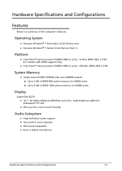
... 1.6 GHz, DDR3 2GB, 3.5 W) (for models with DDR3 support only) Intel Atom™ Series processor N2800 (1MB L2 cache, 1.86 GHz, DDR3 4GB, 6.5 W) System Memory 0 Single-channel DDR3 SDRAM with one soDIMM module: Up to 2 GB of DDR3-800 system... memory for N2600 series Up to 4 GB of DDR3-1066 system memory for N2800 series Display 0 Aspire One D270 10.1" SD 1024 x 600 pixel (WSVGA) resolution , high-brightness (200-...
... 1.6 GHz, DDR3 2GB, 3.5 W) (for models with DDR3 support only) Intel Atom™ Series processor N2800 (1MB L2 cache, 1.86 GHz, DDR3 4GB, 6.5 W) System Memory 0 Single-channel DDR3 SDRAM with one soDIMM module: Up to 2 GB of DDR3-800 system... memory for N2600 series Up to 4 GB of DDR3-1066 system memory for N2800 series Display 0 Aspire One D270 10.1" SD 1024 x 600 pixel (WSVGA) resolution , high-brightness (200-...
Acer Aspire One D270 Service Guide
Page 16
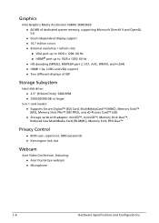
...GB or larger 5-in-1 card reader: Supports Secure Digital™ (SD) Card, MultiMediaCard™ (MMC), Memory Stick™ (MS), Memory Stick PRo™ (MS PRO), and xD-Picture Card™ (xD) Storage cards with adapter: miniSD™, ...microSD™, Memory Stick Duo™, Reduced-Size MultiMedia Card (RS-MMC), Memory Stick PRO Duo™ Privacy Control 0 BIOS user, supervisor, HDD passwords Kensington lock slot Webcam 0 Acer Video Conference, featuring: Acer Crystal Eye webcam &#...
...GB or larger 5-in-1 card reader: Supports Secure Digital™ (SD) Card, MultiMediaCard™ (MMC), Memory Stick™ (MS), Memory Stick PRo™ (MS PRO), and xD-Picture Card™ (xD) Storage cards with adapter: miniSD™, ...microSD™, Memory Stick Duo™, Reduced-Size MultiMedia Card (RS-MMC), Memory Stick PRO Duo™ Privacy Control 0 BIOS user, supervisor, HDD passwords Kensington lock slot Webcam 0 Acer Video Conference, featuring: Acer Crystal Eye webcam &#...
Acer Aspire One D270 Service Guide
Page 36
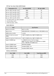
...100°C SPL Spec (dBA) 26 29 31 34 N/A System Memory Item Specification Memory controller Built in at CPU Memory size DDRIII 800/1066 2 GB (N2600 series), 4 GB (N2800 series) DIMM socket number 2 socket Supports memory size per socket 2 GB for N2600 series, 4GB for N2800 series ... DIMM Speed 800/1066 SODIMM Support DIMM voltage Standard JEDEC 1.5V Supports DIMM package Standard JEDEC 204-pin Memory Combinations Slot 1 (MB) 1024 2048 Slot 2 (MB) N/A N/A Total Memory (MB) 1024 2048 1-26 Hardware Specifications and Configurations Fan Off = 50°C 4200 Fan on =...
...100°C SPL Spec (dBA) 26 29 31 34 N/A System Memory Item Specification Memory controller Built in at CPU Memory size DDRIII 800/1066 2 GB (N2600 series), 4 GB (N2800 series) DIMM socket number 2 socket Supports memory size per socket 2 GB for N2600 series, 4GB for N2800 series ... DIMM Speed 800/1066 SODIMM Support DIMM voltage Standard JEDEC 1.5V Supports DIMM package Standard JEDEC 204-pin Memory Combinations Slot 1 (MB) 1024 2048 Slot 2 (MB) N/A N/A Total Memory (MB) 1024 2048 1-26 Hardware Specifications and Configurations Fan Off = 50°C 4200 Fan on =...
Acer Aspire One D270 Service Guide
Page 41
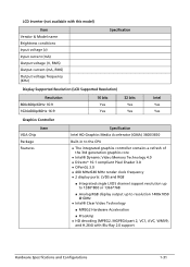
...) 3600/3650 Built-in to the CPU The integrated graphics controller contains a refresh of the 3rd generation graphics core Intel® Dynamic Video Memory Technology 4.0 Directx* 10.1 compliant Pixel Shader 3.0 OPenGL 3.0 400 MHz/640 MHz render clock frequency 2 display ports: LVDS and RGB Integrated...
...) 3600/3650 Built-in to the CPU The integrated graphics controller contains a refresh of the 3rd generation graphics core Intel® Dynamic Video Memory Technology 4.0 Directx* 10.1 compliant Pixel Shader 3.0 OPenGL 3.0 400 MHz/640 MHz render clock frequency 2 display ports: LVDS and RGB Integrated...
Acer Aspire One D270 Service Guide
Page 43
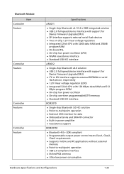
...KByte data RAM and 512 KByte program ROM On-chip low power oscillator On-chip one-time programmable(OTP) memory Standard USB HCI interface BCM2070 Single-chip Bluetooth 3.0 HCI solution Point-to-multipoint operation ...EDR compliant Programmable output power control meets Class1, Class2, Class3 requirements Supports mobile and PC applications without external memory Point-to-multipoint operation USB 2.0 compliant interface Etched PCB antenna Ultra-low power consumption Hardware Specifications ...
...KByte data RAM and 512 KByte program ROM On-chip low power oscillator On-chip one-time programmable(OTP) memory Standard USB HCI interface BCM2070 Single-chip Bluetooth 3.0 HCI solution Point-to-multipoint operation ...EDR compliant Programmable output power control meets Class1, Class2, Class3 requirements Supports mobile and PC applications without external memory Point-to-multipoint operation USB 2.0 compliant interface Etched PCB antenna Ultra-low power consumption Hardware Specifications ...
Acer Aspire One D270 Service Guide
Page 47
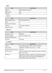
...-240Vac, 50-60Hz, input current ~1.7 Amps 264 Vrms 264 Vac (Cold/Hot start) No damage; Hardware Specifications and Configurations 1-37 VRAM Item Chipset Memory size Interface Specification N/A (Shared memory only) N/A N/A USB Port Item USB compliance level EHCI Number of USB port(s) Location Output Current Specification Universal Serial Bus 2.0 2 3 1 left side, 2 right side...
...-240Vac, 50-60Hz, input current ~1.7 Amps 264 Vrms 264 Vac (Cold/Hot start) No damage; Hardware Specifications and Configurations 1-37 VRAM Item Chipset Memory size Interface Specification N/A (Shared memory only) N/A N/A USB Port Item USB compliance level EHCI Number of USB port(s) Location Output Current Specification Universal Serial Bus 2.0 2 3 1 left side, 2 right side...

Acer Aspire One D270 Service Guide
Page 48
... and hard disc may be power managed in 1 card reader, supporting: Secure Digital™ (SD) Card, MultiMediaCard™ (MMC), Memory Stick™ (MS), Memory Stick PRo™ (MS PRO), and xD-Picture Card™ (xD) Storage cards with adapter:, microSD™...;, Memory Stick Duo™, Reduced-Size MultiMedia Card (RS-MMC), Memory Stick PRO Duo™ 1-38 Hardware Specifications and Configurations All devices in the system are turned off completely. OS initiated...
... and hard disc may be power managed in 1 card reader, supporting: Secure Digital™ (SD) Card, MultiMediaCard™ (MMC), Memory Stick™ (MS), Memory Stick PRo™ (MS PRO), and xD-Picture Card™ (xD) Storage cards with adapter:, microSD™...;, Memory Stick Duo™, Reduced-Size MultiMedia Card (RS-MMC), Memory Stick PRO Duo™ 1-38 Hardware Specifications and Configurations All devices in the system are turned off completely. OS initiated...
Acer Aspire One D270 Service Guide
Page 49
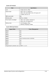
... color off: System off Full charging = Blue Battery charging = Amber System DMA Specification Legacy Mode Power Management DMA0 N/A DMA1 N/A DMA2 N/A DMA3 N/A DMA4 Direct memory access controller DMA5 N/A DMA6 N/A DMA7 N/A *ExpressCard controller can use DMA 1, 2, or 5.
... color off: System off Full charging = Blue Battery charging = Amber System DMA Specification Legacy Mode Power Management DMA0 N/A DMA1 N/A DMA2 N/A DMA3 N/A DMA4 Direct memory access controller DMA5 N/A DMA6 N/A DMA7 N/A *ExpressCard controller can use DMA 1, 2, or 5.
Acer Aspire One D270 Service Guide
Page 50
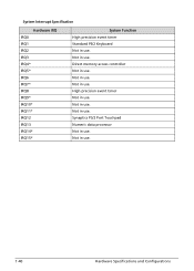
Not in use. Not in use. High precision event timer Not in use. Direct memory access controller Not in use. Not in use. System Interrupt Specification Hardware IRQ IRQ0 IRQ1 IRQ2 IRQ3 IRQ4* IRQ5* IRQ6 IRQ7* IRQ8 IRQ9* IRQ10* IRQ11* IRQ12 IRQ13 IRQ14* IRQ15* System Function High precision event timer Standard PS/2 Keyboard Not in use. 1-40 Hardware Specifications and Configurations Not in use . Not in use . Not in use . Synaptics PS/2 Port Touchpad Numeric data processor Not in use .
Not in use. Not in use. High precision event timer Not in use. Direct memory access controller Not in use. Not in use. System Interrupt Specification Hardware IRQ IRQ0 IRQ1 IRQ2 IRQ3 IRQ4* IRQ5* IRQ6 IRQ7* IRQ8 IRQ9* IRQ10* IRQ11* IRQ12 IRQ13 IRQ14* IRQ15* System Function High precision event timer Standard PS/2 Keyboard Not in use. 1-40 Hardware Specifications and Configurations Not in use . Not in use . Not in use . Synaptics PS/2 Port Touchpad Numeric data processor Not in use .
Acer Aspire One D270 Service Guide
Page 52
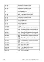
... - 405F 4060 - 407F 4080 - 408F 4090 - 4097 4098 - 409F 40A0 - 40A7 40A8 - 40AB 40AC - 40AF Programmable interrupt controller Programmable interrupt controller Programmable interrupt controller Direct memory access controller Numeric data processor Intel(R) Graphics Media Accelerator 3150 Intel(R) Graphics Media Accelerator 3150 Motherboard resources Programmable interrupt controller Motherboard resources Motherboard resources Motherboard...
... - 405F 4060 - 407F 4080 - 408F 4090 - 4097 4098 - 409F 40A0 - 40A7 40A8 - 40AB 40AC - 40AF Programmable interrupt controller Programmable interrupt controller Programmable interrupt controller Direct memory access controller Numeric data processor Intel(R) Graphics Media Accelerator 3150 Intel(R) Graphics Media Accelerator 3150 Motherboard resources Programmable interrupt controller Motherboard resources Motherboard resources Motherboard...
Acer Aspire One D270 Service Guide
Page 58
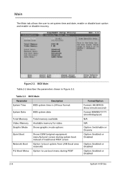
... system time in Figure 2-2. Figure 2-2. BIOS Main Table 2-2 describes the parameters shown in 24-hour format System Date BIOS system date Total Memory Video Memory Graphic Mode Total memory available Available memory for video Shows graphic mode options Quiet Boot Network Boot F12 Boot Menu Shows OEM (original equipment manufacturer) screen during system boot...
... system time in Figure 2-2. Figure 2-2. BIOS Main Table 2-2 describes the parameters shown in 24-hour format System Date BIOS system date Total Memory Video Memory Graphic Mode Total memory available Available memory for video Shows graphic mode options Quiet Boot Network Boot F12 Boot Menu Shows OEM (original equipment manufacturer) screen during system boot...

Acer Aspire One D270 Service Guide
Page 66
...61548;Restore a BIOS when it becomes corrupted. Copy Flash Utility to update the system BIOS Flash ROM. BIOS Flash Utilities 0 BIOS Flash memory updates are required for the following to finish loading BIOS Flash, do not boot system. NOTE: NOTE: Flash Utility has auto execution function.... 2-14 System Utilities NOTE: NOTE: Do not install memory related drivers (XMS, EMS, DPMI) when Flash is used . Use the Flash utility to bootable USB HDD. 3. Prepare a bootable USB HDD. ...
...61548;Restore a BIOS when it becomes corrupted. Copy Flash Utility to update the system BIOS Flash ROM. BIOS Flash Utilities 0 BIOS Flash memory updates are required for the following to finish loading BIOS Flash, do not boot system. NOTE: NOTE: Flash Utility has auto execution function.... 2-14 System Utilities NOTE: NOTE: Do not install memory related drivers (XMS, EMS, DPMI) when Flash is used . Use the Flash utility to bootable USB HDD. 3. Prepare a bootable USB HDD. ...
Acer Aspire One D270 Service Guide
Page 72
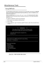
... shows Verifying DMI pool data, it is checking that the table correlates with the hardware before sending information to EEPROM (Electrically Erasable Programmable Read-Only Memory). Miscellaneous Tools 0 Using DMITools 0 The DMI (Desktop Management Interface) Tool copies BIOS information to the operating system (Windows, etc.). Figure 2-22. Boot to DOS. 3. Used...
... shows Verifying DMI pool data, it is checking that the table correlates with the hardware before sending information to EEPROM (Electrically Erasable Programmable Read-Only Memory). Miscellaneous Tools 0 Using DMITools 0 The DMI (Desktop Management Interface) Tool copies BIOS information to the operating system (Windows, etc.). Figure 2-22. Boot to DOS. 3. Used...
Acer Aspire One D270 Service Guide
Page 76
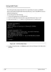
... excute stuuid20.exe under DOS mode. (Figure 2-28) 3. Figure 2-28. UUID Tool Main Screen 4. Unzip UUID package tool to EEPROM (Electrically Erasable Programmable Read-Only Memory). Execute stuuid20 s 1 0 (where 1 is the PCI bus and 0 is the device ID). At the command prompt, run VEEPROM.exe to the EEPROM. 2-24 System Utilities...
... excute stuuid20.exe under DOS mode. (Figure 2-28) 3. Figure 2-28. UUID Tool Main Screen 4. Unzip UUID package tool to EEPROM (Electrically Erasable Programmable Read-Only Memory). Execute stuuid20 s 1 0 (where 1 is the PCI bus and 0 is the device ID). At the command prompt, run VEEPROM.exe to the EEPROM. 2-24 System Utilities...

Acer Aspire One D270 Service Guide
Page 80
... 3-16 3G Module Removal 3-17 3G Module Installation 3-17 WLAN (Wireless Local Area Network) Module Removal . . . .3-18 WLAN Module Installation 3-18 DIMM (Dual In-line Memory Module) Removal 3-19 DIMM Installation 3-19 Upper Case Removal 3-20 Upper Case Installation 3-21 Bluetooth Module Removal 3-22 Bluetooth Module Installation 3-22 Mainboard Removal 3-23...
... 3-16 3G Module Removal 3-17 3G Module Installation 3-17 WLAN (Wireless Local Area Network) Module Removal . . . .3-18 WLAN Module Installation 3-18 DIMM (Dual In-line Memory Module) Removal 3-19 DIMM Installation 3-19 Upper Case Removal 3-20 Upper Case Installation 3-21 Bluetooth Module Removal 3-22 Bluetooth Module Installation 3-22 Mainboard Removal 3-23...
Acer Aspire One D270 Service Guide
Page 97
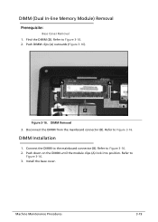
Find the DIMM (D). Refer to Figure 3-10. 2. Push down on the DIMM until the module clips (A) lock into position. DIMM Installation 0 1. Machine Maintenance Procedures 3-19 Disconnect the DIMM from the mainboard connector (B). Refer to Figure 3-16. 2. DIMM Removal 3. Connect the DIMM to Figure 3-16. Install the base cover. Push DIMM clips (A) outwards (Figure 3-16). A A B Figure 3-16. DIMM (Dual In-line Memory Module) Removal 0 Prerequisite: Base Cover Removal 1. Refer to the mainboard connector (B). Refer to Figure 3-16. 3.
Find the DIMM (D). Refer to Figure 3-10. 2. Push down on the DIMM until the module clips (A) lock into position. DIMM Installation 0 1. Machine Maintenance Procedures 3-19 Disconnect the DIMM from the mainboard connector (B). Refer to Figure 3-16. 2. DIMM Removal 3. Connect the DIMM to Figure 3-16. Install the base cover. Push DIMM clips (A) outwards (Figure 3-16). A A B Figure 3-16. DIMM (Dual In-line Memory Module) Removal 0 Prerequisite: Base Cover Removal 1. Refer to the mainboard connector (B). Refer to Figure 3-16. 3.


