
AL922 Monitor Service Guide
Page 1
... 2.2 Lcd Monitor General Specification...4 2.3 Lcd Panel Specification ...5 2.4 Input Signals ...11 2.5 Controls ...15 2.6 White Color Temperature ...17 2.7 Power Supply ...18 2.8 Plug & Play(Edid)...18 2.9 Audio Technical Specification ...19 3. DC/DC POWER and Audio CKT VM-902 29 6.1 Input:...29 6.2 Output: ...29 6.3 Efficiency...29 6.4 Connector Locations...29 7. VK901 Control Panel Board ...25 4.1 Description...25 4.2 Connector and Switch Locations ...25 4.3 Connector type ...25 4.4 Connector pin Assignment ...25 4.5 Switch definition...26 4.6 LED definition...26 5. INVERTER BOARD...27...
... 2.2 Lcd Monitor General Specification...4 2.3 Lcd Panel Specification ...5 2.4 Input Signals ...11 2.5 Controls ...15 2.6 White Color Temperature ...17 2.7 Power Supply ...18 2.8 Plug & Play(Edid)...18 2.9 Audio Technical Specification ...19 3. DC/DC POWER and Audio CKT VM-902 29 6.1 Input:...29 6.2 Output: ...29 6.3 Efficiency...29 6.4 Connector Locations...29 7. VK901 Control Panel Board ...25 4.1 Description...25 4.2 Connector and Switch Locations ...25 4.3 Connector type ...25 4.4 Connector pin Assignment ...25 4.5 Switch definition...26 4.6 LED definition...26 5. INVERTER BOARD...27...
AL922 Monitor Service Guide
Page 3
... concerns. 1. It also supports VESA DPMS power management and plug & play function. INTRODUCTION 1.1 Scope This specification defines the requirements for the 19" MICRO-PROCESSOR based Multimode supported high resolution color LCD monitor, This monitor can be directly connected to provide a performance oriented product with the latest LCD technology to general 15 pin D-sub VGA connector and DVI-D digital connector, eliminates the requirement of optional special display card. It is also a space...
... concerns. 1. It also supports VESA DPMS power management and plug & play function. INTRODUCTION 1.1 Scope This specification defines the requirements for the 19" MICRO-PROCESSOR based Multimode supported high resolution color LCD monitor, This monitor can be directly connected to provide a performance oriented product with the latest LCD technology to general 15 pin D-sub VGA connector and DVI-D digital connector, eliminates the requirement of optional special display card. It is also a space...

AL922 Monitor Service Guide
Page 4
FUJITSU FLC48SXC8V Display size : 376.32mm(H) x 301.056mm(V) Display mode : VGA 720 X 400 (70 Hz) VGA 640 X 480 (60/66/70/72/75 Hz) SVGA 800 X 600 (60/70/72/75 Hz) 4 Minolta CA100 photometer, or equivalent Maximum (unless otherwise specified ) Typical (unless otherwise specified ) User red/white balance, Green/white balance and Blue/white balance control: Power input : In the center (unless otherwise specified ) 110Vac or...
FUJITSU FLC48SXC8V Display size : 376.32mm(H) x 301.056mm(V) Display mode : VGA 720 X 400 (70 Hz) VGA 640 X 480 (60/66/70/72/75 Hz) SVGA 800 X 600 (60/70/72/75 Hz) 4 Minolta CA100 photometer, or equivalent Maximum (unless otherwise specified ) Typical (unless otherwise specified ) User red/white balance, Green/white balance and Blue/white balance control: Power input : In the center (unless otherwise specified ) 110Vac or...
AL922 Monitor Service Guide
Page 5
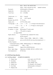
...; Display Area • Pixel Pitch • Display Color active matrix color TFT LCD 1280 x 1024 pixels 1280 x (RGB) x 1024 376.32mm(H) x 301.056mm(V) 0.098x3mm(H) x 0.294mm(V) 16777216 5 Digital TMDS Signal connector : 15 pin Mini D type, (standard VGA video) DVI-D connector Audio power : 1Wrms + 1Wrms ( 300Hz - 10kHz (S.P.L. - 10 dB)) Front control : power on/off with LED select (up, down) adjustment (+,-) Interface frequency Horizontal Frequency 24KHz --80KHz(analog), 31.5- 80KHz(digital) Vertical Frequency 56Hz ----75Hz Plug & play : Support VESA DDC2B functions Power Input...
...; Display Area • Pixel Pitch • Display Color active matrix color TFT LCD 1280 x 1024 pixels 1280 x (RGB) x 1024 376.32mm(H) x 301.056mm(V) 0.098x3mm(H) x 0.294mm(V) 16777216 5 Digital TMDS Signal connector : 15 pin Mini D type, (standard VGA video) DVI-D connector Audio power : 1Wrms + 1Wrms ( 300Hz - 10kHz (S.P.L. - 10 dB)) Front control : power on/off with LED select (up, down) adjustment (+,-) Interface frequency Horizontal Frequency 24KHz --80KHz(analog), 31.5- 80KHz(digital) Vertical Frequency 56Hz ----75Hz Plug & play : Support VESA DDC2B functions Power Input...
AL922 Monitor Service Guide
Page 11
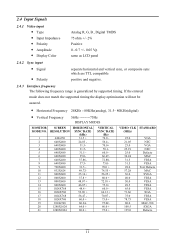
... 135.0 VGA NEC VGA NEC Defacto MAC VESA VESA Text Defacto MAC SVGA VESA VESA VESA VESA XGA VESA VESA MAC-768 SXGA Defacto 11 2.4 Input Signals 2.4.1 Video input • Type • Input Impedance • Polarity • Amplitude • Display Color Analog R, G, B., Digital TMDS 75 ohm +/- 2% Positive 0 - 0.7 +/- 0.05 Vp same as LCD panel 2.4.2 Sync input • Signal • Polarity separate horizontal and vertical sync, or composite sync which are TTL compatible positive and negative. 2.4.3 Interface frequency The following frequency range is generalized by supported timing.
... 135.0 VGA NEC VGA NEC Defacto MAC VESA VESA Text Defacto MAC SVGA VESA VESA VESA VESA XGA VESA VESA MAC-768 SXGA Defacto 11 2.4 Input Signals 2.4.1 Video input • Type • Input Impedance • Polarity • Amplitude • Display Color Analog R, G, B., Digital TMDS 75 ohm +/- 2% Positive 0 - 0.7 +/- 0.05 Vp same as LCD panel 2.4.2 Sync input • Signal • Polarity separate horizontal and vertical sync, or composite sync which are TTL compatible positive and negative. 2.4.3 Interface frequency The following frequency range is generalized by supported timing.
AL922 Monitor Service Guide
Page 16
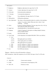
...; H. Horizontal position adjustment. • V. Exit OSD menu function. Current mode vertical frequency±1Hz. It takes 3-5 seconds to 100. Set CIE coordinate at 9300°K color temperature. The range is from 0 to 100 scales. Firmware revision. 16 OSD position adjustment. Green signal gain by user defined. Sharpness : Adjust the scale-up effect(smoother or sharper.) OSD Transparency: Adjust the transparency level of language for description, including (English, German, French, Spanish, Italian) Recall the default...
...; H. Horizontal position adjustment. • V. Exit OSD menu function. Current mode vertical frequency±1Hz. It takes 3-5 seconds to 100. Set CIE coordinate at 9300°K color temperature. The range is from 0 to 100 scales. Firmware revision. 16 OSD position adjustment. Green signal gain by user defined. Sharpness : Adjust the scale-up effect(smoother or sharper.) OSD Transparency: Adjust the transparency level of language for description, including (English, German, French, Spanish, Italian) Recall the default...
AL922 Monitor Service Guide
Page 17
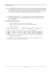
... 9300, 7500,6500 and User, Default value of color setting Color Color Coordinate Temp. If no further signal, then it shows "No Signal" and enter power saving mode. 2.6 White Color Temperature White color temperature is maximum setting for this mode whenever encounter this mode and switch to optimized condition automatically for panel. Total 21 recent used modes are recorded into AL922(AM999) VESA DPMS Functionality When signaled by the host CPU, AL922(AM999) show a black screen about 3 seconds. v' 0.446...
... 9300, 7500,6500 and User, Default value of color setting Color Color Coordinate Temp. If no further signal, then it shows "No Signal" and enter power saving mode. 2.6 White Color Temperature White color temperature is maximum setting for this mode whenever encounter this mode and switch to optimized condition automatically for panel. Total 21 recent used modes are recorded into AL922(AM999) VESA DPMS Functionality When signaled by the host CPU, AL922(AM999) show a black screen about 3 seconds. v' 0.446...
AL922 Monitor Service Guide
Page 25
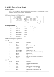
... LED-Y LED-G GND KEY-POWER KEY-DOWN KEY-R KEY-L KEY-UP GND 4.4.2 J6 Pin NO. 1 2 3 4 5 Signal VOL GND LIN1 RIN1 RIN2 Maker E&T E&T ACER ACER SC Number of pins 10 11 2 2 9 Comment NC Power saving mode Monitor is ON GND Power ON/OFF key Function select counter-clockwise key Adjust up key Adjust down key Function select counter-clockwise key GND Comment Volume ON/OFF Control GND Audio Volume Adjust...
... LED-Y LED-G GND KEY-POWER KEY-DOWN KEY-R KEY-L KEY-UP GND 4.4.2 J6 Pin NO. 1 2 3 4 5 Signal VOL GND LIN1 RIN1 RIN2 Maker E&T E&T ACER ACER SC Number of pins 10 11 2 2 9 Comment NC Power saving mode Monitor is ON GND Power ON/OFF key Function select counter-clockwise key Adjust up key Adjust down key Function select counter-clockwise key GND Comment Volume ON/OFF Control GND Audio Volume Adjust...
AL922 Monitor Service Guide
Page 51
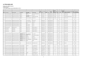
... CABLE 1 ET.92202.1009 LAM999F1009 CABLE LCD NET WIR SET KEY BOARD CABLE CABLE SINGLE CABLE SINGLE CABLE POWER CORD POWER CORD POWER CORD POWER CORD NET WIR SET H-CON SET CB ASY CB ASY CB ASY POWER CORD( EU) POWER CORD( AU) POWER CORD (EU) POWER CORD (EU) CASE/COVER/BRACKET 1 ET.92202.001/004/005/009 LAM999F1002/1004/1005/1009 ASSEMBLY LCD COVER ASSY CASE/COVER/BRACKET LCD BEZEL A'SSY 1 ET.92202.001/004/005/009 LAM999F1002/1004/1005/1009 ASSEMBLY (ACER) CASE/COVER...
... CABLE 1 ET.92202.1009 LAM999F1009 CABLE LCD NET WIR SET KEY BOARD CABLE CABLE SINGLE CABLE SINGLE CABLE POWER CORD POWER CORD POWER CORD POWER CORD NET WIR SET H-CON SET CB ASY CB ASY CB ASY POWER CORD( EU) POWER CORD( AU) POWER CORD (EU) POWER CORD (EU) CASE/COVER/BRACKET 1 ET.92202.001/004/005/009 LAM999F1002/1004/1005/1009 ASSEMBLY LCD COVER ASSY CASE/COVER/BRACKET LCD BEZEL A'SSY 1 ET.92202.001/004/005/009 LAM999F1002/1004/1005/1009 ASSEMBLY (ACER) CASE/COVER...
AL922 Monitor Service Guide
Page 55
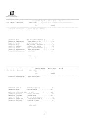
PART NO. PART NO. DESCRIPTION SPECIFICATION F1 001 REMARKS # LAM999F1001 LAM999F ABO-USA UR+TCO99 110V MSV16 19"FUJITSU 1 DC190020440 CB ASY 2 GA050000400 POWER CORD SET 3 PK10V000000 AC ADAP 4 DC190019270 CB ASY 5 DC190013720 CABLE ASSY 6 58290330001 DIS ABO 7 68006530001 PACKING ABO-USA ...MAC LCDMONITOR 1 - - - - 008 8 HF6VS558110 WARRANTY CARD F-VS558-ABO USA LCD/CRT R1 1 - - - - 013 9 EJ1AM999000 FRONT PLATE N-AM999-ABO FOR BEZEL 1 - - - - 014 End of Report QUANTITY REQUIRED DWG.NO. 680065 REV. 0A C NO. LAM999 REV. 0A C NO. \\M-id\ART1\ MANUAL\service...
PART NO. PART NO. DESCRIPTION SPECIFICATION F1 001 REMARKS # LAM999F1001 LAM999F ABO-USA UR+TCO99 110V MSV16 19"FUJITSU 1 DC190020440 CB ASY 2 GA050000400 POWER CORD SET 3 PK10V000000 AC ADAP 4 DC190019270 CB ASY 5 DC190013720 CABLE ASSY 6 58290330001 DIS ABO 7 68006530001 PACKING ABO-USA ...MAC LCDMONITOR 1 - - - - 008 8 HF6VS558110 WARRANTY CARD F-VS558-ABO USA LCD/CRT R1 1 - - - - 013 9 EJ1AM999000 FRONT PLATE N-AM999-ABO FOR BEZEL 1 - - - - 014 End of Report QUANTITY REQUIRED DWG.NO. 680065 REV. 0A C NO. LAM999 REV. 0A C NO. \\M-id\ART1\ MANUAL\service...
AL922 Monitor Service Guide
Page 59
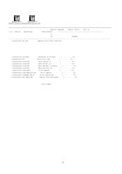
...\ART1\ MANUAL\service\ABMANUAL\service\AB QUANTITY REQUIRED DWG.NO. 582903 REV. 0A C NO. VM-902 LAM999F 1 - - - - 352 9 461A7830011 FIRMWARE CTRL/B VL-901 LAM999F ABO 1 - - - - 353 10 X66AI930001 MEC PARTS ABO LAM999F TCO99 MSV16/MBK17 1 - - - - 354 End of Report 59 PART NO. DESCRIPTION SPECIFICATION 30 001 REMARKS # 58290330001 DIS ABO LAM999F TCO99 19"FUJ 1280X1024 1 AC600022700 LCD MODU...
...\ART1\ MANUAL\service\ABMANUAL\service\AB QUANTITY REQUIRED DWG.NO. 582903 REV. 0A C NO. VM-902 LAM999F 1 - - - - 352 9 461A7830011 FIRMWARE CTRL/B VL-901 LAM999F ABO 1 - - - - 353 10 X66AI930001 MEC PARTS ABO LAM999F TCO99 MSV16/MBK17 1 - - - - 354 End of Report 59 PART NO. DESCRIPTION SPECIFICATION 30 001 REMARKS # 58290330001 DIS ABO LAM999F TCO99 19"FUJ 1280X1024 1 AC600022700 LCD MODU...
AL922 Monitor Service Guide
Page 63
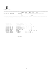
...LED 2 CF150021100 VR RES 3 DA1M999V110 PCB 4 DC030040000 WAFER CONN 5 DC03E000500 WAFER CONN. 6 DC03E001000 WAFER CONN. 7 DC230201307 CONNECTOR 8 DE611000607 SWITCH 9 XX0900T2119 JUMPER WIRE 10 XX0900T2135 JUMPER WIRE LYG2093 YEL/GRN 3D 3P 1 - - - - VR1 CM999 VT-901 REV1 1 - - - - J1 SC SCJ-0348-C 3.65D 1 - - - - J2 PT-002-B2 5 - - - - W1 W2 End of Report A 63 \\M-id\ART1\ MANUAL\service...\AB QUANTITY REQUIRED DWG.NO. 454A79 REV. 1A C NO. D1 1/100W 50KB EVUTV6B28C54 1 - - - - J3 J4 E&T 96113-1013 10P P1.25 1 - - - - PART NO. S1 S2 ...
...LED 2 CF150021100 VR RES 3 DA1M999V110 PCB 4 DC030040000 WAFER CONN 5 DC03E000500 WAFER CONN. 6 DC03E001000 WAFER CONN. 7 DC230201307 CONNECTOR 8 DE611000607 SWITCH 9 XX0900T2119 JUMPER WIRE 10 XX0900T2135 JUMPER WIRE LYG2093 YEL/GRN 3D 3P 1 - - - - VR1 CM999 VT-901 REV1 1 - - - - J1 SC SCJ-0348-C 3.65D 1 - - - - J2 PT-002-B2 5 - - - - W1 W2 End of Report A 63 \\M-id\ART1\ MANUAL\service...\AB QUANTITY REQUIRED DWG.NO. 454A79 REV. 1A C NO. D1 1/100W 50KB EVUTV6B28C54 1 - - - - J3 J4 E&T 96113-1013 10P P1.25 1 - - - - PART NO. S1 S2 ...
AL922 Monitor Service Guide
Page 75
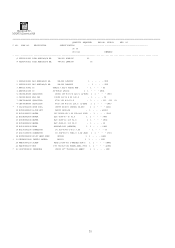
... P3.5 - 3 - - - DESCRIPTION SPECIFICATION 30 30 001 021 REMARKS # 455A7830001 PCBA AUDIO&D/D BD. ZZZ 3 AB015170002 IC TDA1517 SIL-9 AUDIO AMP. - 1 - - - \\M-id\ART1\ MANUAL\service\AB QUANTITY REQUIRED DWG.NO. 455A78 REV. 0C C NO. PART NO. L801 16 DC230201200 CONNECTOR SC SCJ-0345-1-X-S 3.6D - 1 ... WAFER E&T 4500-11 11P P2.0 - 1 - - - J3 17 DC231100300 CONNECTOR SC SCD-014-1 PIN2.0 6.3D JACK 1 1 - - - J801 18 ECCM9943000 DC-DC HEAT SINK CM9943 1 1 - - - ZZZ 20 MAA70007209 SCREW M3X0.5+10P-NI & WASHER DIM 6 1 1 - - - &H801 21 MD2T0001109...
... P3.5 - 3 - - - DESCRIPTION SPECIFICATION 30 30 001 021 REMARKS # 455A7830001 PCBA AUDIO&D/D BD. ZZZ 3 AB015170002 IC TDA1517 SIL-9 AUDIO AMP. - 1 - - - \\M-id\ART1\ MANUAL\service\AB QUANTITY REQUIRED DWG.NO. 455A78 REV. 0C C NO. PART NO. L801 16 DC230201200 CONNECTOR SC SCJ-0345-1-X-S 3.6D - 1 ... WAFER E&T 4500-11 11P P2.0 - 1 - - - J3 17 DC231100300 CONNECTOR SC SCD-014-1 PIN2.0 6.3D JACK 1 1 - - - J801 18 ECCM9943000 DC-DC HEAT SINK CM9943 1 1 - - - ZZZ 20 MAA70007209 SCREW M3X0.5+10P-NI & WASHER DIM 6 1 1 - - - &H801 21 MD2T0001109...
AL922 User Guide
Page 1
... that only the supplied signal cord be determined by turning the equipment off and on a circuit different from Its Stand 2 Interface for Arm Applications...3 Cable Installation...3 Connecting the Display to your Computer 3 Connecting the AC Power...3 Connecting the Audio Cable ...3 Setting Up the LCD Monitor...4 Power Management System ...4 Chapter 2 Display Controls 4 User Controls ...4 Adjusting the Monitor's Display...4 Function Description ...5 Chapter 3 Technical Information 7 Specifications ...7 Standard Timing Table...9 Troubleshooting ...9 Preface This manual is encouraged to...
... that only the supplied signal cord be determined by turning the equipment off and on a circuit different from Its Stand 2 Interface for Arm Applications...3 Cable Installation...3 Connecting the Display to your Computer 3 Connecting the AC Power...3 Connecting the Audio Cable ...3 Setting Up the LCD Monitor...4 Power Management System ...4 Chapter 2 Display Controls 4 User Controls ...4 Adjusting the Monitor's Display...4 Function Description ...5 Chapter 3 Technical Information 7 Specifications ...7 Standard Timing Table...9 Troubleshooting ...9 Preface This manual is encouraged to...
AL922 User Guide
Page 2
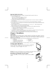
... spilled into LCD Monitor or the monitor has been exposed to rain. * LCD Monitor or the case is designed to allow users to -PC DVI-D Cable * 1.8M Power Cord * 1.5M Stereo Jack Audio Cable If you unpack the LCD Monitor, make sure that the Monitor does not become too hot. Attempting this range could result in the box: * LCD Monitor * User's Manual * 1.8M Monitor-to-PC VGA Cable * AC Adapter * 1.8M Monitor-to have a comfortable viewing angle.
... spilled into LCD Monitor or the monitor has been exposed to rain. * LCD Monitor or the case is designed to allow users to -PC DVI-D Cable * 1.8M Power Cord * 1.5M Stereo Jack Audio Cable If you unpack the LCD Monitor, make sure that the Monitor does not become too hot. Attempting this range could result in the box: * LCD Monitor * User's Manual * 1.8M Monitor-to-PC VGA Cable * AC Adapter * 1.8M Monitor-to have a comfortable viewing angle.
AL922 User Guide
Page 3
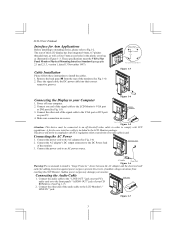
... Computer 1. Power off -the-shelf video cable in the LCD Monitor package. Connect the AC adapter's DC output connector to the DC Power Jack of the monitor.(See Fig. 1-4) 2. Place the signal cable, the DC power cable into their correct respective grooves. AL922 User's Manual Interface for adding protection against power surges to prevent the errects of the audio cable to the LCD Monitor's " LINE IN " jack. These specifications meet the VESA Flat Panel Monitor Physical Mounting Interface...
... Computer 1. Power off -the-shelf video cable in the LCD Monitor package. Connect the AC adapter's DC output connector to the DC Power Jack of the monitor.(See Fig. 1-4) 2. Place the signal cable, the DC power cable into their correct respective grooves. AL922 User's Manual Interface for adding protection against power surges to prevent the errects of the audio cable to the LCD Monitor's " LINE IN " jack. These specifications meet the VESA Flat Panel Monitor Physical Mounting Interface...
AL922 User Guide
Page 4
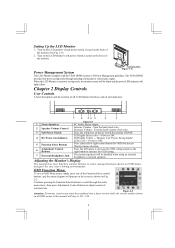
... Volume - Press the soft power switch to select among functions shown on the back of selected item. Turn on the LCD monitor's hard power switch, located on OSD menu, designed for OSD (On Screen Display) menu selection. LED lights Green color --- Monitor is in power saving mode, the monitor screen will be blank and the power LED indicator will be disabled when using an external headphone or external speakers. Press the left or right control button for easy user-viewing environments. Power is in "Power Saving Mode". signal. Turn...
... Volume - Press the soft power switch to select among functions shown on the back of selected item. Turn on the LCD monitor's hard power switch, located on OSD menu, designed for OSD (On Screen Display) menu selection. LED lights Green color --- Monitor is in power saving mode, the monitor screen will be blank and the power LED indicator will be disabled when using an external headphone or external speakers. Press the left or right control button for easy user-viewing environments. Power is in "Power Saving Mode". signal. Turn...
AL922 User Guide
Page 5
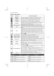
... description. AL922 User's Manual Function Description Ico n Function Brightness Contrast H. This function let's you adjust the display size, clock and phase to activate the selected function, Auto Adjustment, Use Analog Input or Use Digital Input. A total of 256 scales (0 to 255) are the same, this setting and exits the OSD menu function. Because the H and V-Frequencies of this function let's you adjust the display's horizontal position V. Five OSD language options are available. Auto and Input Select Exit Press button...
... description. AL922 User's Manual Function Description Ico n Function Brightness Contrast H. This function let's you adjust the display size, clock and phase to activate the selected function, Auto Adjustment, Use Analog Input or Use Digital Input. A total of 256 scales (0 to 255) are the same, this setting and exits the OSD menu function. Because the H and V-Frequencies of this function let's you adjust the display's horizontal position V. Five OSD language options are available. Auto and Input Select Exit Press button...
AL922 User Guide
Page 7
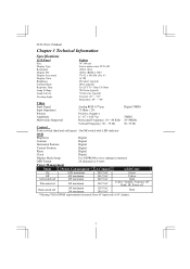
...+85° Horizontal: -85° ~ +85° Video Input Signal Analog RGB 0.7Vp-p Digital TMDS Input Impedance 75 Ohm ± 2% Polarity Positive, Negative Amplitude 0 - 0.7 ± 0.05 Vp TMDS Multi-mode Supported Horizontal Frequency: 24 ~ 80 KHz 24~80KHz Vertical Frequency: 56 ~ 75 Hz 56~75 Hz Control Power switch (hard and soft types) On/Off switch with LED indicator OSD Brightness Digital Contrast Digital Horizontal Position Digital Vertical Position Digital Phase Digital Clock Digital Display Mode Setup Use EEPROM to save settings in memory OSD Format 20...
...+85° Horizontal: -85° ~ +85° Video Input Signal Analog RGB 0.7Vp-p Digital TMDS Input Impedance 75 Ohm ± 2% Polarity Positive, Negative Amplitude 0 - 0.7 ± 0.05 Vp TMDS Multi-mode Supported Horizontal Frequency: 24 ~ 80 KHz 24~80KHz Vertical Frequency: 56 ~ 75 Hz 56~75 Hz Control Power switch (hard and soft types) On/Off switch with LED indicator OSD Brightness Digital Contrast Digital Horizontal Position Digital Vertical Position Digital Phase Digital Clock Digital Display Mode Setup Use EEPROM to save settings in memory OSD Format 20...
AL922 User Guide
Page 9
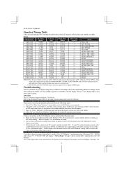
... LCD Monitor is selected. If step 2 doesn't work, connect your PC system to see if there's any black vertical stripes appear. Move to "Phase" function in OSD menu again and adjust the monitor screen to an alternative mode listed in the Standard Timing Table or replace the VGA card, and then repeat steps 1 and 2. Freq. (Hz) Pixel Freq. (MHz) H/V Sync. Please change to its most suitable available timing. AL922 User's Manual...
... LCD Monitor is selected. If step 2 doesn't work, connect your PC system to see if there's any black vertical stripes appear. Move to "Phase" function in OSD menu again and adjust the monitor screen to an alternative mode listed in the Standard Timing Table or replace the VGA card, and then repeat steps 1 and 2. Freq. (Hz) Pixel Freq. (MHz) H/V Sync. Please change to its most suitable available timing. AL922 User's Manual...


