User Manual
Page 1
Table of Contents English Preface ...2 FCC Statement Warning ...2 Canadian DOC Notice ...2 Important Safety Instructions...3 Special Notes on LCD Monitors 3 Chapter 1 Installation ...4 Unpacking...4 Viewing Angle Adjustment ...4 Detaching LCD Monitor from Its Stand 4 Interface for Arm Applications ...5 Connecting the Display...5 Connecting the AC Power ...5 Power Management System...5 Chapter 2 Display Controls 6 General Instructions...6 Front Panel Control ...7 How to Adjust a Setting...8 Adjusting the Picture ...8 Chapter 3 Technical Information 10 Specifications...10 ...
Table of Contents English Preface ...2 FCC Statement Warning ...2 Canadian DOC Notice ...2 Important Safety Instructions...3 Special Notes on LCD Monitors 3 Chapter 1 Installation ...4 Unpacking...4 Viewing Angle Adjustment ...4 Detaching LCD Monitor from Its Stand 4 Interface for Arm Applications ...5 Connecting the Display...5 Connecting the AC Power ...5 Power Management System...5 Chapter 2 Display Controls 6 General Instructions...6 Front Panel Control ...7 How to Adjust a Setting...8 Adjusting the Picture ...8 Chapter 3 Technical Information 10 Specifications...10 ...

User Manual
Page 2
This document contains proprietary information protected by one or more of the following measures: • Reposition or relocate the receiving antenna. • Increase the separation between the equipment and the receiver. • Connect the equipment into an outlet on , the user is encouraged to try to which can radiate radio frequency energy, and if not installed and used in accordance with the limits for comliance could void your authority to radio communications. All rights are cautioned that interference will not occur in a particular installation. FCC Statement Warning This ...
This document contains proprietary information protected by one or more of the following measures: • Reposition or relocate the receiving antenna. • Increase the separation between the equipment and the receiver. • Connect the equipment into an outlet on , the user is encouraged to try to which can radiate radio frequency energy, and if not installed and used in accordance with the limits for comliance could void your authority to radio communications. All rights are cautioned that interference will not occur in a particular installation. FCC Statement Warning This ...

User Manual
Page 3
Important Safety Instructions Please read the following symptoms are normal with dampened rag. 2. To clean LCD Monitor screen; -- Servicing of the fluorescent light, the screen may flicker during initial use . • The LCD screen has effective pixels of the following occurs, immediately unplug your monitor and call an authorized technician. * Monitor to PC signal cable is frayed or damaged. * Liquid spilled into LCD Monitor or the monitor has been exposed to rain. * LCD Monitor or the case is recovered slowly by changing the image or turning off the Power Switch for hours. 3 Only...
Important Safety Instructions Please read the following symptoms are normal with dampened rag. 2. To clean LCD Monitor screen; -- Servicing of the fluorescent light, the screen may flicker during initial use . • The LCD screen has effective pixels of the following occurs, immediately unplug your monitor and call an authorized technician. * Monitor to PC signal cable is frayed or damaged. * Liquid spilled into LCD Monitor or the monitor has been exposed to rain. * LCD Monitor or the case is recovered slowly by changing the image or turning off the Power Switch for hours. 3 Only...
User Manual
Page 4
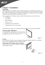
Chapter 1 Installation Unpacking Before unpacking the LCD Monitor, prepare a suitable workspace for sufficient airflow. Make sure that LCD Monitor has enough space around it for your dealer immediately. The viewing angle can be adjusted from Its Stand Unscrew screws the swivel base support column and pull down the hinge to +15°.(See fig. 1-1) Figure 1-1 Warning Do not force the LCD Monitor over its maximum viewing angle settings as stated above. Though the LCD Monitor uses very little power, some ventilation is needed to ensure that any of these items is designed to allow users ...
Chapter 1 Installation Unpacking Before unpacking the LCD Monitor, prepare a suitable workspace for sufficient airflow. Make sure that LCD Monitor has enough space around it for your dealer immediately. The viewing angle can be adjusted from Its Stand Unscrew screws the swivel base support column and pull down the hinge to +15°.(See fig. 1-1) Figure 1-1 Warning Do not force the LCD Monitor over its maximum viewing angle settings as stated above. Though the LCD Monitor uses very little power, some ventilation is needed to ensure that any of these items is designed to allow users ...

User Manual
Page 5
Power off your PC. 4. Make sure connections are secure. Connect the power cord to Fig.1-2. Interface for Arm Applications Before installing to mounting device, please refer to an AC power source. Connecting the Display 1. The VESA DPMS provides four power saving modes through detecting a horizontal or vertical sync. Connecting the AC Power 1. Connect one end of this LCD display has four integrated 4 mm, 0.7 pitches threaded nuts, as well as four 5 mm access holes in the plastic covering as illustrated in power saving mode, the monitor screen will be blank and the power ...
Power off your PC. 4. Make sure connections are secure. Connect the power cord to Fig.1-2. Interface for Arm Applications Before installing to mounting device, please refer to an AC power source. Connecting the Display 1. The VESA DPMS provides four power saving modes through detecting a horizontal or vertical sync. Connecting the AC Power 1. Connect one end of this LCD display has four integrated 4 mm, 0.7 pitches threaded nuts, as well as four 5 mm access holes in the plastic covering as illustrated in power saving mode, the monitor screen will be blank and the power ...
User Manual
Page 6
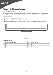
z The power cord should be adjusted to your personal preferences. z Press the power button to turn the monitor on the monitor position. Chapter 2 Display Controls General Instructions Press the power button to turn on or off. z Connect the video cable from the monitor to the video card. The power indicator will light up. The other control buttons are located at front panel of the monitor (See Figure 2-1). External Controls 1 Auto Adjust Key/Exit 2 < 3 > Figure 2-1 4 MENU/ENTER 5 LED 6 / Power Key 6 By changing these settings, the picture can be connected.
z The power cord should be adjusted to your personal preferences. z Press the power button to turn the monitor on the monitor position. Chapter 2 Display Controls General Instructions Press the power button to turn on or off. z Connect the video cable from the monitor to the video card. The power indicator will light up. The other control buttons are located at front panel of the monitor (See Figure 2-1). External Controls 1 Auto Adjust Key/Exit 2 < 3 > Figure 2-1 4 MENU/ENTER 5 LED 6 / Power Key 6 By changing these settings, the picture can be connected.
User Manual
Page 7
The Auto Adjustment function is used to turn the monitor ON or OFF, And display the monitor's state. Never use strong solvents such as thinner, benzene, or abrasive cleaners, since these will come in active status, this button for 2 seconds to direct sunlight, or excessive dust or mechanical vibration or shock. ‧ Save the original shipping carton and packing materials, as EXIT-KEY (EXIT OSD menu). 2. off status, press this button will act as they will damage the cabinet. When OSD menu is in handy if you ever have to ship your monitor. ‧ For maximum protection, ...
The Auto Adjustment function is used to turn the monitor ON or OFF, And display the monitor's state. Never use strong solvents such as thinner, benzene, or abrasive cleaners, since these will come in active status, this button for 2 seconds to direct sunlight, or excessive dust or mechanical vibration or shock. ‧ Save the original shipping carton and packing materials, as EXIT-KEY (EXIT OSD menu). 2. off status, press this button will act as they will damage the cabinet. When OSD menu is in handy if you ever have to ship your monitor. ‧ For maximum protection, ...

User Manual
Page 8
Adjusts the background brightness of the screen image. User / Blue 8 Press < or > to Adjust a Setting 1. To exit and save, select the exit function. User / Green Adjusts Red/Green/Blue intensity. How to change the settings of the current function. 5. Position Adjust picture Focus V. Press < or > to activate the OSD window. 2. Press the MENU-button to select the function that you want to adjust any other function, repeat steps 2-4. (option) Adjusting the Picture The descriptions for function control LEDS Main Menu Icon Sub Menu Icon Sub Menu Item Contrast ...
Adjusts the background brightness of the screen image. User / Blue 8 Press < or > to Adjust a Setting 1. To exit and save, select the exit function. User / Green Adjusts Red/Green/Blue intensity. How to change the settings of the current function. 5. Position Adjust picture Focus V. Press < or > to activate the OSD window. 2. Press the MENU-button to select the function that you want to adjust any other function, repeat steps 2-4. (option) Adjusting the Picture The descriptions for function control LEDS Main Menu Icon Sub Menu Icon Sub Menu Item Contrast ...
User Manual
Page 9
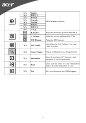
N/A Source Change Analog and Digital source change.(option) N/A Information N/A Reset Show the resolution, H/V frequency and input port of Auto-configuration and set the color temperature to Cool. Clear each old status of current input timing. Position Multi-language selection. OSD Timeout Adjust the OSD timeout. Position Adjust the vertical position of picture. N/A Auto Config Auto Adjust the H/V Position, Focus and Clock of the OSD. V. Adjust the horizontal position of the OSD. N/A Exit Save user adjustment and OSD disappear. 9 N/A English N/A N/A Deutsch ...
N/A Source Change Analog and Digital source change.(option) N/A Information N/A Reset Show the resolution, H/V frequency and input port of Auto-configuration and set the color temperature to Cool. Clear each old status of current input timing. Position Multi-language selection. OSD Timeout Adjust the OSD timeout. Position Adjust the vertical position of picture. N/A Auto Config Auto Adjust the H/V Position, Focus and Clock of the OSD. V. Adjust the horizontal position of the OSD. N/A Exit Save user adjustment and OSD disappear. 9 N/A English N/A N/A Deutsch ...
User Manual
Page 10
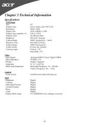
Chapter 3 Technical Information Specifications LCD Panel Size Display Type Resolution Display Dot Display Area (mm)(H x V) Display Color Brightness Contrast Ratio Response Time Lamp Voltage Lamp Current Viewing Angle Video Input Signal Input Impedance Polarity Amplitude Multi-mode Supported Control Power switch OSD Brightness Contrast Horizontal Position Vertical Position Phase Clock Display Mode Setup 24" Active matrix color TFT LCD 1920 x 1200 1920 x (RGB) x 1200 518.4 x 324.0 16.2M (ture 8bit) 500 cd/m2 (typical) 1000:1 (typical & IL = 6mA) 6ms (Gray to Gray) 1800 Vrms (typical) 6.0 mA ...
Chapter 3 Technical Information Specifications LCD Panel Size Display Type Resolution Display Dot Display Area (mm)(H x V) Display Color Brightness Contrast Ratio Response Time Lamp Voltage Lamp Current Viewing Angle Video Input Signal Input Impedance Polarity Amplitude Multi-mode Supported Control Power switch OSD Brightness Contrast Horizontal Position Vertical Position Phase Clock Display Mode Setup 24" Active matrix color TFT LCD 1920 x 1200 1920 x (RGB) x 1200 518.4 x 324.0 16.2M (ture 8bit) 500 cd/m2 (typical) 1000:1 (typical & IL = 6mA) 6ms (Gray to Gray) 1800 Vrms (typical) 6.0 mA ...
User Manual
Page 11
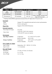
Sync Input Signal Polarity Plug & Play Separate TTL compatible horizontal and vertical synchronization Positive and negative Supports VESA DDC2B functions External Connection Power Input (AC input) Video Cable AC socket 1.8M with 15-pin D-sub connector 1.8M with DVI connector (option) Environment Operating Condition: Storage Condition: Temperature Relative Humidity Temperature Relative Humidity 5°C to 40°C/41°F to 104°F 20% to 80% -20°C to 60° C/-4°F to140° F 5% to 85% Power Supply (AC Input) Input Voltage Input Current Single phase, 100 ~ 240VAC...
Sync Input Signal Polarity Plug & Play Separate TTL compatible horizontal and vertical synchronization Positive and negative Supports VESA DDC2B functions External Connection Power Input (AC input) Video Cable AC socket 1.8M with 15-pin D-sub connector 1.8M with DVI connector (option) Environment Operating Condition: Storage Condition: Temperature Relative Humidity Temperature Relative Humidity 5°C to 40°C/41°F to 104°F 20% to 80% -20°C to 60° C/-4°F to140° F 5% to 85% Power Supply (AC Input) Input Voltage Input Current Single phase, 100 ~ 240VAC...
User Manual
Page 12
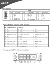
Pin Assignment 6 PIN 1 11 1 2 5 15 3 4 10 5 Description Red Green Blue Digital GND Digital GND Signal PIN Description 6 Red Rtn 7 Green Rtn 8 Blue Rtn 9 +5V 10 Hot Plug Detect PIN Description 11 NC 12 SDA 13 H. D (option) Pin - Assignment of DVI -D connector : 1 TX2- 9 TX1- 2 TX2+ 10 TX1+ 3 Shield (TX2 / TX4) 11 Shield (TX1 / TX3) 4 NC 12 NC 5 NC 13 NC 6 DDC-Serial Clock 14 +5V power *) 7 DDC-Serial Data 15 Ground (+5V) 8 NC 16 Hot plug detect Pin assignment for DVI - Sync. 15 SCL Digital Video Input Connector : DVI - Sync. 14 V. D Connector (...
Pin Assignment 6 PIN 1 11 1 2 5 15 3 4 10 5 Description Red Green Blue Digital GND Digital GND Signal PIN Description 6 Red Rtn 7 Green Rtn 8 Blue Rtn 9 +5V 10 Hot Plug Detect PIN Description 11 NC 12 SDA 13 H. D (option) Pin - Assignment of DVI -D connector : 1 TX2- 9 TX1- 2 TX2+ 10 TX1+ 3 Shield (TX2 / TX4) 11 Shield (TX1 / TX3) 4 NC 12 NC 5 NC 13 NC 6 DDC-Serial Clock 14 +5V power *) 7 DDC-Serial Data 15 Ground (+5V) 8 NC 16 Hot plug detect Pin assignment for DVI - Sync. 15 SCL Digital Video Input Connector : DVI - Sync. 14 V. D Connector (...
User Manual
Page 13
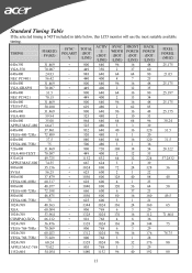
Standard Timing Table If the selected timing is NOT included in table below, this LCD monitor will use the most suitable available timing. TIMING FH(KHZ) FV(HZ) SYNC POLARIT Y TOTAL (DOT /LINE) ACTIV E (DOT /LINE) SYNC WIDTH (DOT /LINE) FRONT PORCH (DOT /LINE) BACK PORCH (DOT /LINE) PIXEL FOREQ. (MHZ) 640x350 31.469 + 800 640 96 16 48 25.175 VGA-350 70.087 - 449 350 2 37 60 640x400 24.83 - 848 640 64 64 80 21.05 NEC PC9801 56.42 - 440 400 8 7 25 640x400 31.469 - 800 640 96 16 48 25.175 VGA-GRAPH 70.087 + 449 400 2 12 35 640x400 ...
Standard Timing Table If the selected timing is NOT included in table below, this LCD monitor will use the most suitable available timing. TIMING FH(KHZ) FV(HZ) SYNC POLARIT Y TOTAL (DOT /LINE) ACTIV E (DOT /LINE) SYNC WIDTH (DOT /LINE) FRONT PORCH (DOT /LINE) BACK PORCH (DOT /LINE) PIXEL FOREQ. (MHZ) 640x350 31.469 + 800 640 96 16 48 25.175 VGA-350 70.087 - 449 350 2 37 60 640x400 24.83 - 848 640 64 64 80 21.05 NEC PC9801 56.42 - 440 400 8 7 25 640x400 31.469 - 800 640 96 16 48 25.175 VGA-GRAPH 70.087 + 449 400 2 12 35 640x400 ...
User Manual
Page 14
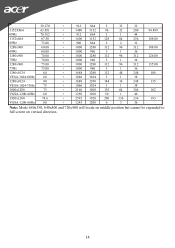
59.270 + 912 864 3 13 32 1152X864 60Hz 63.851 70.012 + 1480 1152 96 32 200 94.499 + 912 864 3 1 44 1152x864 60Hz 67.50 75.00 + 1600 1152 128 64 256 108.00 + 900 864 2 2 32 1280x960 60.00 + 1800 1280 112 96 312 108.00 60Hz 60.00 + 1000 960 3 1 36 1280x960 70Hz 70.00 70.00 + 1800 1280 112 96 312 126.00 + 1000 960 3 1 36 1280x960 75Hz 75.00 75.00 + 1800 1280 112 96 312 135.00 + 1000 960 3 1 36 1280x1024 64 + 1688 1280 112 48 248 108 VESA-1024-60Hz 60 + 1066 1024 3 1 38 1280x1024 80 + 1688 1280 144 16 248 135...
59.270 + 912 864 3 13 32 1152X864 60Hz 63.851 70.012 + 1480 1152 96 32 200 94.499 + 912 864 3 1 44 1152x864 60Hz 67.50 75.00 + 1600 1152 128 64 256 108.00 + 900 864 2 2 32 1280x960 60.00 + 1800 1280 112 96 312 108.00 60Hz 60.00 + 1000 960 3 1 36 1280x960 70Hz 70.00 70.00 + 1800 1280 112 96 312 126.00 + 1000 960 3 1 36 1280x960 75Hz 75.00 75.00 + 1800 1280 112 96 312 135.00 + 1000 960 3 1 36 1280x1024 64 + 1688 1280 112 48 248 108 VESA-1024-60Hz 60 + 1066 1024 3 1 38 1280x1024 80 + 1688 1280 144 16 248 135...

User Manual
Page 15
Check the screen to its most clear display. 4. If step 2 doesn't work, connect your PC system Functions properly with the LCD Monitor, the output timing of the VGA card may initially experience an unstable or unclear display whenever a new display mode or new VGA card is outside of the LCD Monitor's synchronous range (Horizontal: 24 ~ 80 KHz and Vertical: 49 ~ 75 Hz), the OSD will display a message "No Input Signal". 15 Also, if the signal cable is still no picture, press the Adjustment Control button several times. 3. Refer to the normal PC operating environment. In ...
Check the screen to its most clear display. 4. If step 2 doesn't work, connect your PC system Functions properly with the LCD Monitor, the output timing of the VGA card may initially experience an unstable or unclear display whenever a new display mode or new VGA card is outside of the LCD Monitor's synchronous range (Horizontal: 24 ~ 80 KHz and Vertical: 49 ~ 75 Hz), the OSD will display a message "No Input Signal". 15 Also, if the signal cable is still no picture, press the Adjustment Control button several times. 3. Refer to the normal PC operating environment. In ...
