
AL2416W Service Guide
Page 19
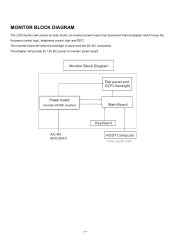
Power board (include: AC/DC,inverter) - 19 - MONITOR BLOCK DIAGRAM The LCD monitor will drive the backlight of panel and the DC-DC conversion. The inverter board will contain an main board, an inverter/ power board, key board and internal adapter which house the flat panel control logic, brightness control logic and DDC. The Adapter will provide thr 12V DC-power to inverter/ power board.
Power board (include: AC/DC,inverter) - 19 - MONITOR BLOCK DIAGRAM The LCD monitor will drive the backlight of panel and the DC-DC conversion. The inverter board will contain an main board, an inverter/ power board, key board and internal adapter which house the flat panel control logic, brightness control logic and DDC. The Adapter will provide thr 12V DC-power to inverter/ power board.

AL2416W Service Guide
Page 29
Features Input Voltage: 100 ~ 240 ±10%Vac Input Frequency: 47 ~ 63Hz Total output power: 110Wmax Inverter brightness adjustment: Burst mode Protection function: auto-recovery type Interface Signals Input AC Inlet: HUAJIE SA-4S-066 or compatible. Function Function 1 +5Vstb +5Vdc for ...) 9 GND Signal ground 10 Power on (24V/5Vcc)Enable signal , Active : 2V~5V, off PIN NO. It supplies the following outputs : 1). 5Vdc: Logic power. 2). 24Vinv: Inverter power. POWER/Inverter Board Description This specification defined the performance and characteristic of power...
Features Input Voltage: 100 ~ 240 ±10%Vac Input Frequency: 47 ~ 63Hz Total output power: 110Wmax Inverter brightness adjustment: Burst mode Protection function: auto-recovery type Interface Signals Input AC Inlet: HUAJIE SA-4S-066 or compatible. Function Function 1 +5Vstb +5Vdc for ...) 9 GND Signal ground 10 Power on (24V/5Vcc)Enable signal , Active : 2V~5V, off PIN NO. It supplies the following outputs : 1). 5Vdc: Logic power. 2). 24Vinv: Inverter power. POWER/Inverter Board Description This specification defined the performance and characteristic of power...

AL2416W Service Guide
Page 30
...Inverter Vcc 2 +24Vcc Inverter Vcc 3 +24Vcc Inverter Vcc 4 +24Vcc Inverter Vcc 5 +24Vcc Inverter Vcc 6 GND Inverter GND 7 GND Inverter GND 8 GND Inverter GND 9 GND Inverter GND 10 GND Inverter GND 11 N.C N.C 12 Backlight Backlight On/Off control signal, connected to CNS1#11 on/off 13 Dimmer Brightness control, connected to 3.3V) 6 ---- ----- 7 Ven Inverter... enable signal from logical board (0V to CN1#12,bright max.=3.3V,min.=0V. 14 N.C N.C 2.Inverter-side connecter : YEONHO 20015 HS-04L or equivalent. ...
...Inverter Vcc 2 +24Vcc Inverter Vcc 3 +24Vcc Inverter Vcc 4 +24Vcc Inverter Vcc 5 +24Vcc Inverter Vcc 6 GND Inverter GND 7 GND Inverter GND 8 GND Inverter GND 9 GND Inverter GND 10 GND Inverter GND 11 N.C N.C 12 Backlight Backlight On/Off control signal, connected to CNS1#11 on/off 13 Dimmer Brightness control, connected to 3.3V) 6 ---- ----- 7 Ven Inverter... enable signal from logical board (0V to CN1#12,bright max.=3.3V,min.=0V. 14 N.C N.C 2.Inverter-side connecter : YEONHO 20015 HS-04L or equivalent. ...

AL2416W Service Guide
Page 31
INVERTER BOARD DESIGNED FOR SAMSUNG LTM240M!-L01 MIN. at 25°C Operating life time -------30% 0V -------3540Vrms 2830Vrms 30,000 hrs 1S 500cd/m2 MAX. 25....
INVERTER BOARD DESIGNED FOR SAMSUNG LTM240M!-L01 MIN. at 25°C Operating life time -------30% 0V -------3540Vrms 2830Vrms 30,000 hrs 1S 500cd/m2 MAX. 25....

AL2416W Service Guide
Page 41
Remove the neck cover. 2. Remove the five screws to release the hinge. 3. Remove the Main Board, Power Board, Inverter and Key Board. (See the next page for detail.) 4. Remove the four screws to release the back cover. 2. Remove the two screws to release the EMI cover from chassis and release the panel. 41 Remove the four screws from chassis. 3. Remove the base Disassemble the chassis 1. Chapter 3 Machine Disassembly and Replacement Disassembly Procedure Disassemble the base 1. Remove the six screws from chassis then take the chassis. 5.
Remove the neck cover. 2. Remove the five screws to release the hinge. 3. Remove the Main Board, Power Board, Inverter and Key Board. (See the next page for detail.) 4. Remove the four screws to release the back cover. 2. Remove the two screws to release the EMI cover from chassis and release the panel. 41 Remove the four screws from chassis. 3. Remove the base Disassemble the chassis 1. Chapter 3 Machine Disassembly and Replacement Disassembly Procedure Disassemble the base 1. Remove the six screws from chassis then take the chassis. 5.

AL2416W Service Guide
Page 42
.... 6. Disassemble two voltage lines from power. 3. Remove the three screws from VL board. 7. Remove the two screws to release VK board from Chassis. 7. Disassemble the Inverter and key board 1. Disassemble power line from Chassis. 8. Remove the four screws from VL board. 6. Disassemble two VL-VK lines from power. 4. 5. Remove the one...
.... 6. Disassemble two voltage lines from power. 3. Remove the three screws from VL board. 7. Remove the two screws to release VK board from Chassis. 7. Disassemble the Inverter and key board 1. Disassemble power line from Chassis. 8. Remove the four screws from VL board. 6. Disassemble two VL-VK lines from power. 4. 5. Remove the one...

AL2416W Service Guide
Page 51
... MODU 2 DC0201933R0 H-CON SET 3 DC0201934R0 H-CON SET 4 DC020193500 H-CON SET 5 DC020193700 H-CON SET 6 NBX30000263 FFC 7 PK07V0033R0 INVERTER 8 PK101V0110I PWR MODU 9 461ACY30001 FIRMWARE CTRL/B 10 454AC830011 PCBA KEY/B 11 X66AUV30001 MEC PARTS ABO LTM240M1-L01-L00 24"B A Acer 1 - - - - 301 AA668 POW-INV 14P 1 - - - - 304 AA668 POW-LOG 12P 1 - - - - 305 AA668 CTRL-KEY 9P...
... MODU 2 DC0201933R0 H-CON SET 3 DC0201934R0 H-CON SET 4 DC020193500 H-CON SET 5 DC020193700 H-CON SET 6 NBX30000263 FFC 7 PK07V0033R0 INVERTER 8 PK101V0110I PWR MODU 9 461ACY30001 FIRMWARE CTRL/B 10 454AC830011 PCBA KEY/B 11 X66AUV30001 MEC PARTS ABO LTM240M1-L01-L00 24"B A Acer 1 - - - - 301 AA668 POW-INV 14P 1 - - - - 304 AA668 POW-LOG 12P 1 - - - - 305 AA668 CTRL-KEY 9P...

AL2416W Service Guide
Page 53
6 MB 461ACY30001 9 Power Board to MB cable AU: 453AC530051 Samsung: 453AC530051 7 Power Board PK101V0110I 8 Inverter Board PK07V0033I0 9 Front Bezel ASSY FAAA6611000 10 Keyboard to MB Cable DC020193500 53
6 MB 461ACY30001 9 Power Board to MB cable AU: 453AC530051 Samsung: 453AC530051 7 Power Board PK101V0110I 8 Inverter Board PK07V0033I0 9 Front Bezel ASSY FAAA6611000 10 Keyboard to MB Cable DC020193500 53