AL1914 LCD Monitor User's Guide
Page 1
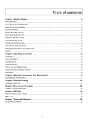
Table of Contents Precautions ...2 Package contents ...3 Installation instructions 3 Assembling the Monitor...3 Detaching the Monitor ...4 Adjusting the Viewing Angle...4 Connecting the Devices...5 Switching the Power ...5 Adjusting display settings 6 External Controls ...6 OSD options ...7 OSD Menu ...7 Troubleshooting ...9 General specifications 10 1
Table of Contents Precautions ...2 Package contents ...3 Installation instructions 3 Assembling the Monitor...3 Detaching the Monitor ...4 Adjusting the Viewing Angle...4 Connecting the Devices...5 Switching the Power ...5 Adjusting display settings 6 External Controls ...6 OSD options ...7 OSD Menu ...7 Troubleshooting ...9 General specifications 10 1
AL1914 LCD Monitor User's Guide
Page 2
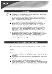
... not allow sharp objects such as knives, pens, or pencils near a source of the cabinet as a missing pixel or a pixel lit all of the monitor. z The LCD screen has effective pixels of radiators, cookers, open fires etc. z When cleaning this does not resolve the problem do not indicate a... the display screen, including sprays. Be aware of the location of 99.99% or more. A cloth very slightly moistened with LCD monitor and do not attempt to injury or death through electrocution among other hazards. z If you find slightly uneven brightness on the screen depending...
... not allow sharp objects such as knives, pens, or pencils near a source of the cabinet as a missing pixel or a pixel lit all of the monitor. z The LCD screen has effective pixels of radiators, cookers, open fires etc. z When cleaning this does not resolve the problem do not indicate a... the display screen, including sprays. Be aware of the location of 99.99% or more. A cloth very slightly moistened with LCD monitor and do not attempt to injury or death through electrocution among other hazards. z If you find slightly uneven brightness on the screen depending...
AL1914 LCD Monitor User's Guide
Page 3
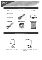
Position the monitor on top of the monitor along the track. 3 Connect the stand into the neck of the stand. 2. LCD Monitor Package contents Power Cord VGA Cable Audio Cable User Manual (CD) Quick Start Guide Installation instructions Assembling the Monitor acer acer 1.
Position the monitor on top of the monitor along the track. 3 Connect the stand into the neck of the stand. 2. LCD Monitor Package contents Power Cord VGA Cable Audio Cable User Manual (CD) Quick Start Guide Installation instructions Assembling the Monitor acer acer 1.
AL1914 LCD Monitor User's Guide
Page 4
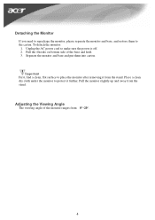
... find a clean, flat surface to protect it from the stand. Place a clean dry cloth under the monitor to place the monitor after removing it further. To detach the monitor: 1. Separate the monitor and base and put them to make sure the power is off. 2. Adjusting the Viewing Angle The viewing ...angle of the base and hold. 3. Detaching the Monitor If you need to repackage the monitor, please separate the monitor and base, and restore them into carton. Pull the 4 hooks on bottom side of the monitor ranges from the stand. Pull the monitor slightly up and away from 0°~20°. 4...
... find a clean, flat surface to protect it from the stand. Place a clean dry cloth under the monitor to place the monitor after removing it further. To detach the monitor: 1. Separate the monitor and base and put them to make sure the power is off. 2. Adjusting the Viewing Angle The viewing ...angle of the base and hold. 3. Detaching the Monitor If you need to repackage the monitor, please separate the monitor and base, and restore them into carton. Pull the 4 hooks on bottom side of the monitor ranges from the stand. Pull the monitor slightly up and away from 0°~20°. 4...
AL1914 LCD Monitor User's Guide
Page 5
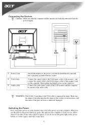
... on the power button go green, this indicates the computer is inserted into a properly grounded electric socket. Connect the audio input socket of the LCD monitor and the computer by means of the VGA cable is trapezoid in shape. Allow about 10 seconds for use. If you see the green light... on the power button or a video signal, check the connections. 5 Switching the Power First, switch the power on to the monitor, then switch the power on to appear. Then tighten the thumbscrews on the connector. Make sure the shape of the plug matches the shape of...
... on the power button go green, this indicates the computer is inserted into a properly grounded electric socket. Connect the audio input socket of the LCD monitor and the computer by means of the VGA cable is trapezoid in shape. Allow about 10 seconds for use. If you see the green light... on the power button or a video signal, check the connections. 5 Switching the Power First, switch the power on to the monitor, then switch the power on to appear. Then tighten the thumbscrews on the connector. Make sure the shape of the plug matches the shape of...
AL1914 LCD Monitor User's Guide
Page 6
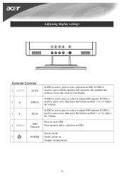
... in OSD. If OSD is inactive, press once, then press the buttons marked < or > to adjust the volume. If OSD is inactive, press and the monitor will automatically optimize the position, focus and clock of your display. Press to select or adjust OSD options. If OSD is inactive, press once, then...
... in OSD. If OSD is inactive, press once, then press the buttons marked < or > to adjust the volume. If OSD is inactive, press and the monitor will automatically optimize the position, focus and clock of your display. Press to select or adjust OSD options. If OSD is inactive, press once, then...
AL1914 LCD Monitor User's Guide
Page 9
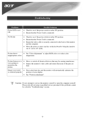
... connected. • Ensure the video cable is securely connected to the back of the monitor and the computer. • Move the mouse or press any key on the keyboard to bring the monitor out of "active off electrical devices that may be solved in the ON position. &#...are bent. Caution: Do not attempt to select color inappropriate colors temperature. Image is not sized • Press select/auto key and the monitor will automatically optimize the or centered properly position of your display. • See "Position adjustment". Please refer all servicing to qualified service ...
... connected. • Ensure the video cable is securely connected to the back of the monitor and the computer. • Move the mouse or press any key on the keyboard to bring the monitor out of "active off electrical devices that may be solved in the ON position. &#...are bent. Caution: Do not attempt to select color inappropriate colors temperature. Image is not sized • Press select/auto key and the monitor will automatically optimize the or centered properly position of your display. • See "Position adjustment". Please refer all servicing to qualified service ...

AL1914 Service Guide
Page 4
... help. Connect the equipment into an outlet on , the user is connected. 4. WARNING: To prevent fire or chock hazard, do not expose the monitor to radio communications. If this product meets the ENERGY STAR® guidelines for a Class B digital device, pursuant to operate the equipment. Reorient or ...our company has determined that changes or modifications not expressly approved by one or more of the FCC Rules. You are present inside the monitor. Do not open the cabinet. Consult the dealer or an experienced radio/TV technician for comliance could viold your authority to Part 15 ...
... help. Connect the equipment into an outlet on , the user is connected. 4. WARNING: To prevent fire or chock hazard, do not expose the monitor to radio communications. If this product meets the ENERGY STAR® guidelines for a Class B digital device, pursuant to operate the equipment. Reorient or ...our company has determined that changes or modifications not expressly approved by one or more of the FCC Rules. You are present inside the monitor. Do not open the cabinet. Consult the dealer or an experienced radio/TV technician for comliance could viold your authority to Part 15 ...
AL1914 Service Guide
Page 5
...not accommodate the three-wire plug, have appropriate configured receptacles marked between 100-240V AC, Min. 3.5A. This plug will protect the monitor from the type of power supplied to protect it will not be used for ventilation. z Do not attempt to qualified service personnel. ...Use only a trolley or stand recommended by the manufacture and follow the kit instructions. Do not place the monitor on an unstable trolley, stand, or table. z Unplug the unit during a lightning storm or when it from overheating, be operated only ...
...not accommodate the three-wire plug, have appropriate configured receptacles marked between 100-240V AC, Min. 3.5A. This plug will protect the monitor from the type of power supplied to protect it will not be used for ventilation. z Do not attempt to qualified service personnel. ...Use only a trolley or stand recommended by the manufacture and follow the kit instructions. Do not place the monitor on an unstable trolley, stand, or table. z Unplug the unit during a lightning storm or when it from overheating, be operated only ...

AL1914 Service Guide
Page 6
... following symptoms are normal with LCD monitor and do not indicate a problem. z The LCD screen has effective pixels of the previous screen may remain after switching the image, when the same image ...
... following symptoms are normal with LCD monitor and do not indicate a problem. z The LCD screen has effective pixels of the previous screen may remain after switching the image, when the same image ...
AL1914 Service Guide
Page 7
Table of contents Chapter 1 Monitor Feature 8 INTRODUCTION...8 ELECTRICAL REQUIREMEENTS...9 MONITOR BLOCK DIAGRAM ...23 BLOCK DIAGRAM ...24 MONITOR BOARD LAYOUT ...27 SOFTWARE FLOW CHART ...29 GENERAL INSTRUCTIONS ...30 SYSTEM INSTALLATION ...31 POWER/INVERTOR BOARD ...36 ELECTRICAL SPECIFICATION...37 INVERTER ELECTRICAL SPECIFICATION ...39 SAFETY ......
Table of contents Chapter 1 Monitor Feature 8 INTRODUCTION...8 ELECTRICAL REQUIREMEENTS...9 MONITOR BLOCK DIAGRAM ...23 BLOCK DIAGRAM ...24 MONITOR BOARD LAYOUT ...27 SOFTWARE FLOW CHART ...29 GENERAL INSTRUCTIONS ...30 SYSTEM INSTALLATION ...31 POWER/INVERTOR BOARD ...36 ELECTRICAL SPECIFICATION...37 INVERTER ELECTRICAL SPECIFICATION ...39 SAFETY ......
AL1914 Service Guide
Page 8
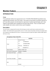
... stereo audio amplifier with volume control to drive a pair of speakers. This monitor can be directly connected to provide a performance oriented product with the latest LCD technology to general 15 pin D-sub VGA connector and eliminates the requirement of AL1914 AL1914 Normal 19" panel LG LM190E03-B4 Panel LG LM190E03-B4N9 Samsung LTM190EX...
... stereo audio amplifier with volume control to drive a pair of speakers. This monitor can be directly connected to provide a performance oriented product with the latest LCD technology to general 15 pin D-sub VGA connector and eliminates the requirement of AL1914 AL1914 Normal 19" panel LG LM190E03-B4 Panel LG LM190E03-B4N9 Samsung LTM190EX...
AL1914 Service Guide
Page 9
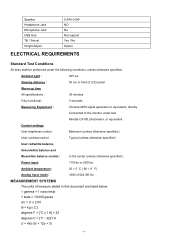
... of LCD panel Warrn up time All specifications : 30 minutes Fully functional : 5 seconds Measuring Equipment : Chroma 2250 signal generator or equivalent, directly Connected to the monitor under the following conditions, unless otherwise specified. Ambient light : 225 lux Viewing distance : 50 cm in front of measure stated in this document are listed...
... of LCD panel Warrn up time All specifications : 30 minutes Fully functional : 5 seconds Measuring Equipment : Chroma 2250 signal generator or equivalent, directly Connected to the monitor under the following conditions, unless otherwise specified. Ambient light : 225 lux Viewing distance : 50 cm in front of measure stated in this document are listed...

AL1914 Service Guide
Page 10
... LM190E03-B4 2). Samsung LTM190EX-L01 4). v' = 9y/(-2x + 12y + 3) x = (27u'/4)/[(9u'/2) - 12v' + 9] y = (3v')/[(9u'/2) - 12v' + 9] nits = cd/(m2) = Ft-L x 3.426 lux = foot-candle x 10.76 LCD monitor General specification Panel Type: 19 " active matrix color TFT LCD 1). LG LM190E03-B4N9 3).
... LM190E03-B4 2). Samsung LTM190EX-L01 4). v' = 9y/(-2x + 12y + 3) x = (27u'/4)/[(9u'/2) - 12v' + 9] y = (3v')/[(9u'/2) - 12v' + 9] nits = cd/(m2) = Ft-L x 3.426 lux = foot-candle x 10.76 LCD monitor General specification Panel Type: 19 " active matrix color TFT LCD 1). LG LM190E03-B4N9 3).

AL1914 Service Guide
Page 21
Monitor should display 85Hz refresh rate mode as emergency mode. Pin assignment for D-sub connector Separate Sync PIN NO. 1 2 3 4 5 6 7 8 9 10 11 12 13 14 15 RED ... - 21 - Support Modes There will be 28 total support modes to accommodate the above mode and other video modes within the frequency range of the monitor. 85Hz refresh rate Support Monitor should display "Out of Range" warning menu at this mode. Video input Connector Analog Video input Connector: 15pins mini D-Sub Table 2.4.5.
Monitor should display 85Hz refresh rate mode as emergency mode. Pin assignment for D-sub connector Separate Sync PIN NO. 1 2 3 4 5 6 7 8 9 10 11 12 13 14 15 RED ... - 21 - Support Modes There will be 28 total support modes to accommodate the above mode and other video modes within the frequency range of the monitor. 85Hz refresh rate Support Monitor should display "Out of Range" warning menu at this mode. Video input Connector Analog Video input Connector: 15pins mini D-Sub Table 2.4.5.

AL1914 Service Guide
Page 22
... unit is switched off and the power of plastic parts: Blue (PC99) 1 6 11 D-sub connector Digital Video Input Connector : DVI - 5 10 15 Color of the monitor is switched on, no voltage may occur at pin 14. - 22 - D Connector: Pin - D (T.B.D) Table 2.4.6 Pin assignment for DVI -
... unit is switched off and the power of plastic parts: Blue (PC99) 1 6 11 D-sub connector Digital Video Input Connector : DVI - 5 10 15 Color of the monitor is switched on, no voltage may occur at pin 14. - 22 - D Connector: Pin - D (T.B.D) Table 2.4.6 Pin assignment for DVI -

AL1914 Service Guide
Page 23
The Adapter will contain an main board, an inverter/ power board, key board and internal adapter which house the flat panel control logic, brightness control logic and DDC. Power board (include: AC/DC,inverter) - 23 - MONITOR BLOCK DIAGRAM The LCD monitor will provide thr 12V DC-power to inverter/ power board. The inverter board will drive the backlight of panel and the DC-DC conversion.
The Adapter will contain an main board, an inverter/ power board, key board and internal adapter which house the flat panel control logic, brightness control logic and DDC. Power board (include: AC/DC,inverter) - 23 - MONITOR BLOCK DIAGRAM The LCD monitor will provide thr 12V DC-power to inverter/ power board. The inverter board will drive the backlight of panel and the DC-DC conversion.
AL1914 Service Guide
Page 30
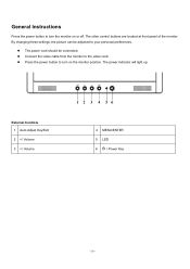
By changing these settings, the picture can be connected. z The power cord should be adjusted to your personal preferences. The power indicator will light up. The other control buttons are located at front panel of the monitor. General Instructions Press the power button to turn on or off. z Press the power button to the video card. z Connect the video cable from the monitor to turn the monitor on the monitor position. External Controls 1 Auto Adjust Key/Exit 2 / Volume 4 MENU/ENTER 5 LED 6 / Power Key - 30 -
By changing these settings, the picture can be connected. z The power cord should be adjusted to your personal preferences. The power indicator will light up. The other control buttons are located at front panel of the monitor. General Instructions Press the power button to turn on or off. z Press the power button to the video card. z Connect the video cable from the monitor to turn the monitor on the monitor position. External Controls 1 Auto Adjust Key/Exit 2 / Volume 4 MENU/ENTER 5 LED 6 / Power Key - 30 -
AL1914 Service Guide
Page 31
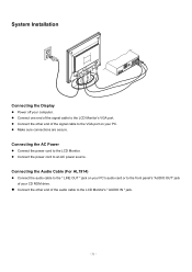
z Connect the other end of the audio cable to the LCD Monitor's " AUDIO IN " jack. - 31 - Connecting the AC Power z Connect the power cord to an AC power source. z Connect the other end of the signal cable ... the " LINE OUT " jack on your computer. z Connect the power cord to the LCD Monitor. System Installation Connecting the Display z Power off your PC. z Make sure connections are secure. Connecting the Audio Cable (For AL1914) z Connect the audio cable to the LCD Monitor's VGA port. z Connect one end of your CD ROM drive.
z Connect the other end of the audio cable to the LCD Monitor's " AUDIO IN " jack. - 31 - Connecting the AC Power z Connect the power cord to an AC power source. z Connect the other end of the signal cable ... the " LINE OUT " jack on your computer. z Connect the power cord to the LCD Monitor. System Installation Connecting the Display z Power off your PC. z Make sure connections are secure. Connecting the Audio Cable (For AL1914) z Connect the audio cable to the LCD Monitor's VGA port. z Connect one end of your CD ROM drive.
AL1914 Service Guide
Page 42
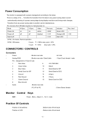
...sync. Transition from any power saving state to avoid unintentionally entering of a power saving stage during display resolution and timing mode changes. Analog RGB : Monitor rear side / Data Cable : 15-pin D-sub female / male Pin - V-Sync. Power-off off off blanked < 3 W Orange LED <...3 W Dark LED SYNC. Assignment of front bezel - 42 - F < 10Hz duty cycle > 25% CONNECTORS / CONTROLS Connectors - Power Consumption The monitor is a delay of 5s ... 7s before the transition from Off-state requires no manual power on active < 60W Green LED -- The recovery from On...
...sync. Transition from any power saving state to avoid unintentionally entering of a power saving stage during display resolution and timing mode changes. Analog RGB : Monitor rear side / Data Cable : 15-pin D-sub female / male Pin - V-Sync. Power-off off off blanked < 3 W Orange LED <...3 W Dark LED SYNC. Assignment of front bezel - 42 - F < 10Hz duty cycle > 25% CONNECTORS / CONTROLS Connectors - Power Consumption The monitor is a delay of 5s ... 7s before the transition from Off-state requires no manual power on active < 60W Green LED -- The recovery from On...


