

AL1715 Service Guide
Page 1
Acer AL1715 Service Guide Service guide files and updates are available on the CSD web: for more information, Please refer to http://csd.acer.com.tw/ - 1 -
Acer AL1715 Service Guide Service guide files and updates are available on the CSD web: for more information, Please refer to http://csd.acer.com.tw/ - 1 -

AL1715 Service Guide
Page 2
... stored in a retrieval system, or translated into any language or computer language, in this guide is a registered trademark of Acer Corporation. Acer Incorporated makes no representations or warranties, either expresses or implied, with respect to change without the prior written permission of merchantability ... holders. - 2 - Pentium and Pentium II/III are trademarks and/or registered trademarks of their purchase, the buyer (and not Acer Incorporated, its distributor, of its dealer) assumes the entire cost of all necessary servicing, repair, and any incidental or consequential damages...
... stored in a retrieval system, or translated into any language or computer language, in this guide is a registered trademark of Acer Corporation. Acer Incorporated makes no representations or warranties, either expresses or implied, with respect to change without the prior written permission of merchantability ... holders. - 2 - Pentium and Pentium II/III are trademarks and/or registered trademarks of their purchase, the buyer (and not Acer Incorporated, its distributor, of its dealer) assumes the entire cost of all necessary servicing, repair, and any incidental or consequential damages...

AL1715 Service Guide
Page 3
... local market requirements and enhance product competitiveness, your regional offices or the responsible personnel/channel to the current topic. add-on your Acer office may have decided to extend the functionality of procedures. In such cases, please contact your regional office MAY have a DIFFERENT ...Denotes actual messages that might result from doing or not doing specific actions. Warning Alerts you to the BASICCONFIGURATION decided for Acer's "global" product offering. this Service Guide provides you with all technical information relating to any damage that appear on screen...
... local market requirements and enhance product competitiveness, your regional offices or the responsible personnel/channel to the current topic. add-on your Acer office may have decided to extend the functionality of procedures. In such cases, please contact your regional office MAY have a DIFFERENT ...Denotes actual messages that might result from doing or not doing specific actions. Warning Alerts you to the BASICCONFIGURATION decided for Acer's "global" product offering. this Service Guide provides you with all technical information relating to any damage that appear on screen...
AL1715 Service Guide
Page 4
Do not open the cabinet. Consult the dealer or an experienced radio/TV technician for energy efficiency. Refer servicing to rain or moisture. However, there is encouraged to try to correct the interference by the party responsible for a Class B digital device, pursuant to Part 15 of the following measures: 1. WARNING: To prevent fire or chock hazard, do not expose the monitor to qualified personnel only. - 4 - This equipment generates, uses and can be determined by turning the equipment off and on a circuit different from that this product meets the ENERGY STAR®...
Do not open the cabinet. Consult the dealer or an experienced radio/TV technician for energy efficiency. Refer servicing to rain or moisture. However, there is encouraged to try to correct the interference by the party responsible for a Class B digital device, pursuant to Part 15 of the following measures: 1. WARNING: To prevent fire or chock hazard, do not expose the monitor to qualified personnel only. - 4 - This equipment generates, uses and can be determined by turning the equipment off and on a circuit different from that this product meets the ENERGY STAR®...
AL1715 Service Guide
Page 5
PRECAUTIONS Do not use the monitor only with UL listed computers which have an electrician install the correct outlet, or use a mounting kit approved by the manufacture or sold with a third (grounding) pin. Do not place the monitor on the monitor. The monitor should be sure these openings are not sure of the type of time. If your dealer or local power company. Do not defeat the safety purpose of power source indicated on the monitor cabinet. Do not overload power strips and extension cords. Please refer all servicing to the appliance. If you to your home, consult...
PRECAUTIONS Do not use the monitor only with UL listed computers which have an electrician install the correct outlet, or use a mounting kit approved by the manufacture or sold with a third (grounding) pin. Do not place the monitor on the monitor. The monitor should be sure these openings are not sure of the type of time. If your dealer or local power company. Do not defeat the safety purpose of power source indicated on the monitor cabinet. Do not overload power strips and extension cords. Please refer all servicing to the appliance. If you to your home, consult...

AL1715 Service Guide
Page 6
In this case, the screen is displayed for hours. - 6 - NOTES Due to the nature of the LCD screen, an afterimage of the fluorescent light, the screen may include blemishes of 0.01% or less such as a missing pixel or a pixel lit all of 99.99% or more. It may flicker during initial use . The LCD screen has effective pixels of the time. Due to the nature of the previous screen may find slightly uneven brightness in the screen depending on again to make sure the flicker disappears. You may remain after switching the image, when the same image is recovered slowly by changing ...
In this case, the screen is displayed for hours. - 6 - NOTES Due to the nature of the LCD screen, an afterimage of the fluorescent light, the screen may include blemishes of 0.01% or less such as a missing pixel or a pixel lit all of 99.99% or more. It may flicker during initial use . The LCD screen has effective pixels of the time. Due to the nature of the previous screen may find slightly uneven brightness in the screen depending on again to make sure the flicker disappears. You may remain after switching the image, when the same image is recovered slowly by changing ...

AL1715 Service Guide
Page 7
Table of contents Chapter 1 Monitor Feature 8 Chapter 2 Operating Instruction 22 Chapter 3 Machine Disassembly and Replacement 30 Chapter 4 Troubleshooting 40 Chapter 5 Connector Information 44 Chapter 6 FRU List 45 Chapter 7 Schematic Diagram 65 - 7 -
Table of contents Chapter 1 Monitor Feature 8 Chapter 2 Operating Instruction 22 Chapter 3 Machine Disassembly and Replacement 30 Chapter 4 Troubleshooting 40 Chapter 5 Connector Information 44 Chapter 6 FRU List 45 Chapter 7 Schematic Diagram 65 - 7 -

AL1715 Service Guide
Page 8
Monitor Feature INTRODUCTION Chapter 1 Scope This specification defines the requirements for analog input DSUB Separate / compatible / AR578 Normal 17" panel HYDIS HT17E12-200 DSUB Separate / compatible / Color Temp user adjust Support Support DDC Speaker Headphone Jack Microphone Jack USB Hub Tilt / Swivel Height Adjust DDC2B 0.5W+0.5W NO No Not support Yes / No Option - 8 - Description The LCD monitor is designed with the latest LCD technology to provide a performance oriented product with volume control to drive a pair of AR577/578 AR577 Panel Normal 17" panel HYDIS HT17E12...
Monitor Feature INTRODUCTION Chapter 1 Scope This specification defines the requirements for analog input DSUB Separate / compatible / AR578 Normal 17" panel HYDIS HT17E12-200 DSUB Separate / compatible / Color Temp user adjust Support Support DDC Speaker Headphone Jack Microphone Jack USB Hub Tilt / Swivel Height Adjust DDC2B 0.5W+0.5W NO No Not support Yes / No Option - 8 - Description The LCD monitor is designed with the latest LCD technology to provide a performance oriented product with volume control to drive a pair of AR577/578 AR577 Panel Normal 17" panel HYDIS HT17E12...

AL1715 Service Guide
Page 9
Minolta CA100 photometer, or equivalent Control settings User brightness control : Maximum (unless otherwise specified ) User contrast control: Typical (unless otherwise specified ) User red/white balance, Green/white balance and Blue/white balance control : In the center (unless otherwise specified ) Power input: 110Vac or 230Vac Ambient temperature: 20 ± 5 ˚C ( 68 ± 9 ˚ F) Analog input mode: 1280 x1024 /60 Hz MEASUREMENT SYSTEMS The units of measure stated in this document are listed below: 1 gamma = 1 nano tesla 1 tesla = 10,000 gauss cm = in front of ...
Minolta CA100 photometer, or equivalent Control settings User brightness control : Maximum (unless otherwise specified ) User contrast control: Typical (unless otherwise specified ) User red/white balance, Green/white balance and Blue/white balance control : In the center (unless otherwise specified ) Power input: 110Vac or 230Vac Ambient temperature: 20 ± 5 ˚C ( 68 ± 9 ˚ F) Analog input mode: 1280 x1024 /60 Hz MEASUREMENT SYSTEMS The units of measure stated in this document are listed below: 1 gamma = 1 nano tesla 1 tesla = 10,000 gauss cm = in front of ...

AL1715 Service Guide
Page 10
Hydis HT17E12-200 Display size: Display mode: Pixel pitch: Display Dot: Pixel Clock: Contrast ratio: θ = 0˚ Brightness: Response time (Tr/Tf): Display color: Viewing angle: Luminance Uniformity: Pc interface: 37.92mm (H) × 270.34mm(V) VGA 720 × 400 (70 Hz) VGA 640 × 480 (60/66/70/72/75 Hz) SVGA 800 × 600 (60/70/72/75 Hz) XGA 1024 × 768 (60/70/75 Hz) SXGA 1280 × 1024 (60/70/75 Hz) standard resolution 0.264mm(H) × 0.264mm(V) 1280 x (RGB) × 1024 25.2 - 135.0MHz HYDIS 430:1 HYDIS:250 HYDIS(20) 16.2M(6 bit color+FRC) HYDIS L / R 80 ...
Hydis HT17E12-200 Display size: Display mode: Pixel pitch: Display Dot: Pixel Clock: Contrast ratio: θ = 0˚ Brightness: Response time (Tr/Tf): Display color: Viewing angle: Luminance Uniformity: Pc interface: 37.92mm (H) × 270.34mm(V) VGA 720 × 400 (70 Hz) VGA 640 × 480 (60/66/70/72/75 Hz) SVGA 800 × 600 (60/70/72/75 Hz) XGA 1024 × 768 (60/70/75 Hz) SXGA 1280 × 1024 (60/70/75 Hz) standard resolution 0.264mm(H) × 0.264mm(V) 1280 x (RGB) × 1024 25.2 - 135.0MHz HYDIS 430:1 HYDIS:250 HYDIS(20) 16.2M(6 bit color+FRC) HYDIS L / R 80 ...

AL1715 Service Guide
Page 11
UNIT 350 430 - - 20 - (total) msec φ=0, θ=0 Normal Viewing Angle CR≥10 200 0.603 0.324 0.262 0.568 0.115 0.077 0.275 0.308 - 250 0.633 0.354 0.292 0.598 0.145 0.107 0.305 0.338 80 80 65 65 - 0.663 0.384 0.322 0.628 0.175 0.137 0.335 0.368 1.2 5 2.0 cd/m2 Degrees % % - 11 - Angle Vert. TYP. MAX. LCD Panel Specification LCD Panel Model (Hydis LT17E12-200) • Display Type • Resolution • Display Dot • Display Area • Pixel Pitch • Display Color • Lamp Voltage • Lamp Current • Weight • Optical ...
UNIT 350 430 - - 20 - (total) msec φ=0, θ=0 Normal Viewing Angle CR≥10 200 0.603 0.324 0.262 0.568 0.115 0.077 0.275 0.308 - 250 0.633 0.354 0.292 0.598 0.145 0.107 0.305 0.338 80 80 65 65 - 0.663 0.384 0.322 0.628 0.175 0.137 0.335 0.368 1.2 5 2.0 cd/m2 Degrees % % - 11 - Angle Vert. TYP. MAX. LCD Panel Specification LCD Panel Model (Hydis LT17E12-200) • Display Type • Resolution • Display Dot • Display Area • Pixel Pitch • Display Color • Lamp Voltage • Lamp Current • Weight • Optical ...
AL1715 Service Guide
Page 12
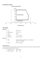
If the entered mode does not match the supported timing the display optimization will not be assured. • Horizontal Frequency • Vertical Frequency 24KHz --80KHz 49Hz -------75Hz - 12 - Panel Relative Humidity Input Signals Video input • Type • Input Impedance • Polarity • Amplitude • Display Color Sync input • Signal • Polarity Analog R, G, B. 75 ohm +/- 2% Positive 0 - 0.7 +/- 0.05 Vp same as LCD panel separate horizontal and vertical sync, or composite sync which are TTL compatible positive and negative. Interface frequency The...
If the entered mode does not match the supported timing the display optimization will not be assured. • Horizontal Frequency • Vertical Frequency 24KHz --80KHz 49Hz -------75Hz - 12 - Panel Relative Humidity Input Signals Video input • Type • Input Impedance • Polarity • Amplitude • Display Color Sync input • Signal • Polarity Analog R, G, B. 75 ohm +/- 2% Positive 0 - 0.7 +/- 0.05 Vp same as LCD panel separate horizontal and vertical sync, or composite sync which are TTL compatible positive and negative. Interface frequency The...

AL1715 Service Guide
Page 13
Supported Timing TIMING 640x350 VGA-350 640x400 NEC PC9801 640x400 VGA-GRAPH 640x400 NEC PC9821 640X480 VESA-PAL 640x480 VGA-480 640x480 APPLE MAC-480 640x480 VESA-480-72Hz 640x480 VESA-480-75Hz 720x400 VGA-400-TEXT 832x624 APPLE MAC-800 800x600 SVGA 800x600 VESA-600-60Hz 800x600 VESA-600-72Hz 800x600 VESA-600-75Hz 1024x768 XGA 1024x768 COMPAQ-XGA 1024x768 VESA-768-70Hz 1024x768 VESA-768-75Hz 1024x768 APPLE MAC-768 1152x864 (60Hz) 1152x864 (70Hz) 1152x864 (75Hz) 1280x960 (60Hz) 1280x960 (70Hz) 1280x960 (75Hz) 1280x1024 VESA-1024-60Hz 1280x1024 VESA-1024-75Hz FH(KHZ) SYNC TOTAL ACTIVE SYNC...
Supported Timing TIMING 640x350 VGA-350 640x400 NEC PC9801 640x400 VGA-GRAPH 640x400 NEC PC9821 640X480 VESA-PAL 640x480 VGA-480 640x480 APPLE MAC-480 640x480 VESA-480-72Hz 640x480 VESA-480-75Hz 720x400 VGA-400-TEXT 832x624 APPLE MAC-800 800x600 SVGA 800x600 VESA-600-60Hz 800x600 VESA-600-72Hz 800x600 VESA-600-75Hz 1024x768 XGA 1024x768 COMPAQ-XGA 1024x768 VESA-768-70Hz 1024x768 VESA-768-75Hz 1024x768 APPLE MAC-768 1152x864 (60Hz) 1152x864 (70Hz) 1152x864 (75Hz) 1280x960 (60Hz) 1280x960 (70Hz) 1280x960 (75Hz) 1280x1024 VESA-1024-60Hz 1280x1024 VESA-1024-75Hz FH(KHZ) SYNC TOTAL ACTIVE SYNC...
AL1715 Service Guide
Page 14
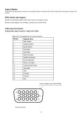
Video input Connector Analog Video input Connector: 15pins mini D-Sub Table 2.4.5. Pin assignment for D-sub connector PIN NO. Separate Sync 1 RED VIDEO 2 GREEN VIDEO 3 BLUE VIDEO 4 GROUND 5 GROUND 6 RED GROUND 7 GREEN GROUND 8 BLUE GROUND 9 PC5V (+5V DDC) 10 CABLE DETECTION 11 GROUND 12 SDA 13 H.SYNC 14 V.SYNC 15 SCL Color of Range" warning menu at this mode. Monitor should display 85Hz refresh rate mode as emergency mode. Support Modes There will be 28 total support modes to accommodate the above mode and other video modes within the frequency ...
Video input Connector Analog Video input Connector: 15pins mini D-Sub Table 2.4.5. Pin assignment for D-sub connector PIN NO. Separate Sync 1 RED VIDEO 2 GREEN VIDEO 3 BLUE VIDEO 4 GROUND 5 GROUND 6 RED GROUND 7 GREEN GROUND 8 BLUE GROUND 9 PC5V (+5V DDC) 10 CABLE DETECTION 11 GROUND 12 SDA 13 H.SYNC 14 V.SYNC 15 SCL Color of Range" warning menu at this mode. Monitor should display 85Hz refresh rate mode as emergency mode. Support Modes There will be 28 total support modes to accommodate the above mode and other video modes within the frequency ...

AL1715 Service Guide
Page 15
Monitor Block Diagram The LCD monitor will provide thr 12V DC-power to inverter/ power board. The Adapter will contain an main board, an inverter/ power board, key board and internal adapter which house the flat panel control logic, brightness control logic and DDC. Power board (include: AC/DC,inverter) - 15 - The inverter board will drive the backlight of panel and the DC-DC conversion.
Monitor Block Diagram The LCD monitor will provide thr 12V DC-power to inverter/ power board. The Adapter will contain an main board, an inverter/ power board, key board and internal adapter which house the flat panel control logic, brightness control logic and DDC. Power board (include: AC/DC,inverter) - 15 - The inverter board will drive the backlight of panel and the DC-DC conversion.

AL1715 Service Guide
Page 19
Are the "" (Adjust key) and power key. 8. Update the lift time of brightness from analog port? 16. Display "Cable Not Connected" message, and go into eeprom. Get the PWM value of back light. 12. Scalar initialize. 10. Does the scalar send out a interrupt request? 14. Read the key board. Check the analog port, are there any signal coming ? 13. Wake up the scalar 15. Are there any signals coming from eeprom. 5. Enter factory mode 9. In standby mode? 11. Program the scalar to be able to green color. Process the OSD display. 19. Program the eeprom by default ...
Are the "" (Adjust key) and power key. 8. Update the lift time of brightness from analog port? 16. Display "Cable Not Connected" message, and go into eeprom. Get the PWM value of back light. 12. Scalar initialize. 10. Does the scalar send out a interrupt request? 14. Read the key board. Check the analog port, are there any signal coming ? 13. Wake up the scalar 15. Are there any signals coming from eeprom. 5. Enter factory mode 9. In standby mode? 11. Program the scalar to be able to green color. Process the OSD display. 19. Program the eeprom by default ...
AL1715 Service Guide
Page 20
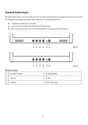
AR577 External Controls 1 Auto Adjust Key/Exit 2 / Volume 4 MENU/ENTER 5 LED 6 / Power Key AR578 - 20 - General Instructions Press the power button to turn on or off. Connect the video cable from the monitor to your personal preferences. The other control buttons are located at front panel of the monitor. Press the power button to turn the monitor on the monitor position. The power cord should be adjusted to the video card. The power indicator will light up. By changing these settings, the picture can be connected.
AR577 External Controls 1 Auto Adjust Key/Exit 2 / Volume 4 MENU/ENTER 5 LED 6 / Power Key AR578 - 20 - General Instructions Press the power button to turn on or off. Connect the video cable from the monitor to your personal preferences. The other control buttons are located at front panel of the monitor. Press the power button to turn the monitor on the monitor position. The power cord should be adjusted to the video card. The power indicator will light up. By changing these settings, the picture can be connected.

AL1715 Service Guide
Page 21
... end of the audio cable to the front panel's "AUDIO OUT" jack of the signal cable to the LCD Monitor. Connecting the Audio Cable (For AL1715 m and AL1715 bm) Connect the audio cable to an AC power source. Connect one end of your computer. Connect the power cord to the " LINE OUT...
... end of the audio cable to the front panel's "AUDIO OUT" jack of the signal cable to the LCD Monitor. Connecting the Audio Cable (For AL1715 m and AL1715 bm) Connect the audio cable to an AC power source. Connect one end of your computer. Connect the power cord to the " LINE OUT...
AL1715 Service Guide
Page 22
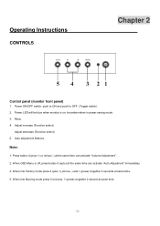
be blue when monitor is off, press button 5 (auto) at same time. 5. Menu. 4. Auto adjustment Buttons. Note: 1. When OSD Menu is on; Press button 4 (plus +),(minus -) and 1 (power) together 2 seconds at the same time can activate "Volume Adjustment". 2. Operating Instructions CONTROLS Chapter 2 Control panel (monitor front panel) 1. Power LED will be amber when in power saving mode. 3. Adjust decrease (Function select). 5. When into Factory mode press 4 (plus +) or (minus -) at same time. - 22 - When into Burning mode press 5 (menus), 1 (power) together 2 ...
be blue when monitor is off, press button 5 (auto) at same time. 5. Menu. 4. Auto adjustment Buttons. Note: 1. When OSD Menu is on; Press button 4 (plus +),(minus -) and 1 (power) together 2 seconds at the same time can activate "Volume Adjustment". 2. Operating Instructions CONTROLS Chapter 2 Control panel (monitor front panel) 1. Power LED will be amber when in power saving mode. 3. Adjust decrease (Function select). 5. When into Factory mode press 4 (plus +) or (minus -) at same time. - 22 - When into Burning mode press 5 (menus), 1 (power) together 2 ...

AL1715 Service Guide
Page 23
Adjust the horizontal position of the 0-100 picture. Reset Value Recall Cool Contrast Value Recall Cool Brightness Value Do Auto Config Do Auto Config Do Auto Config Do Auto Config The Color Temperature will be set to reduce 0-100 Vertical-Line noise. Adjust the verticalposition of the 0-100 picture. Recall Warm Color Temperature N/A from Digital-register. Position V. Main OSD Menu: Outline: The description for control function : Main Menu Sub Menu Sub Menu Description Icon Item Icon Contrast Contrast from EEPROM. Recall Cool Color Temperature from N/A ...
Adjust the horizontal position of the 0-100 picture. Reset Value Recall Cool Contrast Value Recall Cool Brightness Value Do Auto Config Do Auto Config Do Auto Config Do Auto Config The Color Temperature will be set to reduce 0-100 Vertical-Line noise. Adjust the verticalposition of the 0-100 picture. Recall Warm Color Temperature N/A from Digital-register. Position V. Main OSD Menu: Outline: The description for control function : Main Menu Sub Menu Sub Menu Description Icon Item Icon Contrast Contrast from EEPROM. Recall Cool Color Temperature from N/A ...
