
Acer AC100 Service Guide
Page 5
... Rear panel 12 System block diagram 13 Mainboard 15 Mainboard connectors 15 System Jumpers and Switch 16 Hardware removal and installation 17 Disassembly Requirements 17 Pre-disassembly Procedure 17 Disassembly Procedure 18 Removing the Hard Disk 18 Removing the System Cover 20 Removing the Front Bezel 21 Removing the Backplane Board 22 Removing the Fan 25 Removing the HDD Access LED cables 27 Removing the Power Supply 28 Removing the Mainboard Tray 32 Removing the Heatsink 35 Removing the Processor 36 Removing the Memory Modules...
... Rear panel 12 System block diagram 13 Mainboard 15 Mainboard connectors 15 System Jumpers and Switch 16 Hardware removal and installation 17 Disassembly Requirements 17 Pre-disassembly Procedure 17 Disassembly Procedure 18 Removing the Hard Disk 18 Removing the System Cover 20 Removing the Front Bezel 21 Removing the Backplane Board 22 Removing the Fan 25 Removing the HDD Access LED cables 27 Removing the Power Supply 28 Removing the Mainboard Tray 32 Removing the Heatsink 35 Removing the Processor 36 Removing the Memory Modules...

Acer AC100 Service Guide
Page 6
... HDD Access LED cables 60 Reinstalling the Fan 61 Reinstalling the Backplane Board 63 Reinstalling the Front Bezel 66 Reinstalling the System Cover 67 Reinstalling the Hard Disk 68 System diagnostics 73 Hardware Diagnostic Procedure 73 System Check Procedures 74 Power system check 74 System external inspection 74 System internal inspection 74 System Diagnosis 75 Hardware diagnostic program 75 System Status Error Codes 77 BIOS Recovery 77 Clearing CMOS 78 Undetermined Problems 78 BIOS Setup 79 Entering the BIOS Setup Utility...
... HDD Access LED cables 60 Reinstalling the Fan 61 Reinstalling the Backplane Board 63 Reinstalling the Front Bezel 66 Reinstalling the System Cover 67 Reinstalling the Hard Disk 68 System diagnostics 73 Hardware Diagnostic Procedure 73 System Check Procedures 74 Power system check 74 System external inspection 74 System internal inspection 74 System Diagnosis 75 Hardware diagnostic program 75 System Status Error Codes 77 BIOS Recovery 77 Clearing CMOS 78 Undetermined Problems 78 BIOS Setup 79 Entering the BIOS Setup Utility...
Acer AC100 Service Guide
Page 11
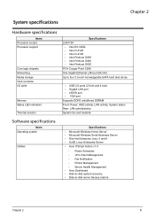
... four 3.5-inch hot-swappable SATA hard disk drives • USB 2.0 ports (2 front and 4 rear) • Gigabit LAN port • eSATA port • VGA port Supports DDR3 unbuffered SDRAM Front: Power, HDD activity, LAN activity, System status Rear: LAN activity/status System fan and heatsink Specifications • Microsoft Windows Home Server • Microsoft Windows Small Business Server • Red Hat Enterprise Linux 5 and 6 • SuSE Linux Enterprise Server • Acer ITSmart Add-in v1.0 • Power Scheduler • vPro Client Management • Fax...
... four 3.5-inch hot-swappable SATA hard disk drives • USB 2.0 ports (2 front and 4 rear) • Gigabit LAN port • eSATA port • VGA port Supports DDR3 unbuffered SDRAM Front: Power, HDD activity, LAN activity, System status Rear: LAN activity/status System fan and heatsink Specifications • Microsoft Windows Home Server • Microsoft Windows Small Business Server • Red Hat Enterprise Linux 5 and 6 • SuSE Linux Enterprise Server • Acer ITSmart Add-in v1.0 • Power Scheduler • vPro Client Management • Fax...

Acer AC100 Service Guide
Page 18
... Mbps link network access 10 Mbps link network access Active network link Transmit or receive activity No network connection 12 Chapter 3 HDD is in the drive bay Rear panel No. LED indicator 4 Power 5 HDD 1 to 4 status Color White None Purple White Purple and white None LED status On Random blink Off On Random blink On Random blink Off Description System is connected to the power supply and turned on and ready for use. • System is booting...
... Mbps link network access 10 Mbps link network access Active network link Transmit or receive activity No network connection 12 Chapter 3 HDD is in the drive bay Rear panel No. LED indicator 4 Power 5 HDD 1 to 4 status Color White None Purple White Purple and white None LED status On Random blink Off On Random blink On Random blink Off Description System is connected to the power supply and turned on and ready for use. • System is booting...

Acer AC100 Service Guide
Page 47
Removing the Expansion Slot Cover 1. Screw (Quantity) M3-0.5*4 NI (1) Color Chrome Torque 5.1 to the expansion card or slot cover. Remove the expansion card or slot cover. See "Removing the Mainboard Tray" on page 32. 2. Rotate the slot cover lock counterclockwise. Disconnect the 26-pin cable connector from its front I /O Board 1. Chapter 5 41 Use a screwdriver to loosen the screw that secures the slot cover lock to 6.9 kgf-cm Part No. 86.1A524.4R0 2. Removing the Front I /O board connector (CN1).
Removing the Expansion Slot Cover 1. Screw (Quantity) M3-0.5*4 NI (1) Color Chrome Torque 5.1 to the expansion card or slot cover. Remove the expansion card or slot cover. See "Removing the Mainboard Tray" on page 32. 2. Rotate the slot cover lock counterclockwise. Disconnect the 26-pin cable connector from its front I /O Board 1. Chapter 5 41 Use a screwdriver to loosen the screw that secures the slot cover lock to 6.9 kgf-cm Part No. 86.1A524.4R0 2. Removing the Front I /O board connector (CN1).

Acer AC100 Service Guide
Page 81
... a bootable USB device by copying or downloading the "ANNIE.GHO" diagnostic utility to the USB device. Power on the rear of the system. 4. The system status indicator blinks red and immediately starts the diagnostic process: a. Fan speed check e. PQAF system test i. After the system has completed the diagnostic procedure the HDD status indicators light purple. If hardware problems, such as a fan, LED board, hard disk drive, memory; are confirmed, the diagnostic program can detect the specific component causing the problem. Test Items Boot from DMI data check l.
... a bootable USB device by copying or downloading the "ANNIE.GHO" diagnostic utility to the USB device. Power on the rear of the system. 4. The system status indicator blinks red and immediately starts the diagnostic process: a. Fan speed check e. PQAF system test i. After the system has completed the diagnostic procedure the HDD status indicators light purple. If hardware problems, such as a fan, LED board, hard disk drive, memory; are confirmed, the diagnostic program can detect the specific component causing the problem. Test Items Boot from DMI data check l.
Acer AC100 Service Guide
Page 82
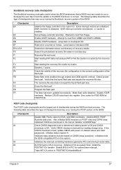
Boot from USB disk HDD 0 HDD 1 HDD 2 HDD 3 HDD 0 HDD 1 HDD 2 HDD 3 Backplane board temperature check PQAF system test PQAF memory test PQAF HDD test Read SN from 0 to initialize different BUSes. After the diagnostic routine is accessed: Checkpoint 2A 38 Description Initialize different buses and perform the following functions: Reset, Detect, and Disable (function 0); Function 0 disables all static devices that are also reserved. Initialize different buses and perform...
Boot from USB disk HDD 0 HDD 1 HDD 2 HDD 3 HDD 0 HDD 1 HDD 2 HDD 3 Backplane board temperature check PQAF system test PQAF memory test PQAF HDD test Read SN from 0 to initialize different BUSes. After the diagnostic routine is accessed: Checkpoint 2A 38 Description Initialize different buses and perform the following functions: Reset, Detect, and Disable (function 0); Function 0 disables all static devices that are also reserved. Initialize different buses and perform...

Acer AC100 Service Guide
Page 83
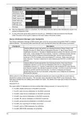
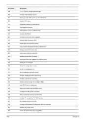
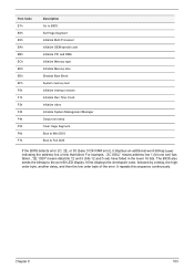
...update is booting System has booted HDD LED error codes 1 2 3 4 Description SATA controller failed USB controller failed LAN controller failed Fan failed Memory failed Boot device not found Disk failure BIOS Recovery Perform the BIOS recovery if the BIOS flash ROM has become corrupted. Unplug the device. The following sections provide instructions on which the different routines are being executed. 'Y' can be from 0 to 5. 0 = Generic DIM (Device Initialization Manager). 1 = On-board System devices. 2 = ISA devices. 3 = EISA devices. 4 = ISA PnP devices. 5 = PCI devices System Status...
...update is booting System has booted HDD LED error codes 1 2 3 4 Description SATA controller failed USB controller failed LAN controller failed Fan failed Memory failed Boot device not found Disk failure BIOS Recovery Perform the BIOS recovery if the BIOS flash ROM has become corrupted. Unplug the device. The following sections provide instructions on which the different routines are being executed. 'Y' can be from 0 to 5. 0 = Generic DIM (Device Initialization Manager). 1 = On-board System devices. 2 = ISA devices. 3 = EISA devices. 4 = ISA PnP devices. 5 = PCI devices System Status...
Acer AC100 Service Guide
Page 84
... Clear CMOS jumper on page 30. 3. Access the BIOS Setup Utility by the computer. Press to the system and reboot automatically after the flash update is completed. 4. Undetermined Problems The diagnostic problems does not identify which adapter or device failed, which installed devices are incorrect, whether a short circuit is suspected, or whether the system is operating correctly. (See "Power system check" on the computer. 5. If any problems are supported by connecting a debug card, keyboard, and a monitor...
... Clear CMOS jumper on page 30. 3. Access the BIOS Setup Utility by the computer. Press to the system and reboot automatically after the flash update is completed. 4. Undetermined Problems The diagnostic problems does not identify which adapter or device failed, which installed devices are incorrect, whether a short circuit is suspected, or whether the system is operating correctly. (See "Power system check" on the computer. 5. If any problems are supported by connecting a debug card, keyboard, and a monitor...

Acer AC100 Service Guide
Page 91
... Support Description Enables or disables the High Precision Event Timer. Parameter Intel VT-d Technology Intel TXT Technology ME Subsystem Configuration Description Option Enables or disables the Intel VT-d Technology. Enabled Disabled Enables or disables the Intel TXT (LT) support. ACPI Configuration This submenu lets you to configure the Intel VT-d Technology and Intel TXT Technology. This submenu is used to set the ME Subsystem Parameters - Enables or disables Windows Hardware Error...
... Support Description Enables or disables the High Precision Event Timer. Parameter Intel VT-d Technology Intel TXT Technology ME Subsystem Configuration Description Option Enables or disables the Intel VT-d Technology. Enabled Disabled Enables or disables the Intel TXT (LT) support. ACPI Configuration This submenu lets you to configure the Intel VT-d Technology and Intel TXT Technology. This submenu is used to set the ME Subsystem Parameters - Enables or disables Windows Hardware Error...

Acer AC100 Service Guide
Page 92
...PCI device to generate SERR#. Enabled Disabled Sets the SATA mode. Parameter PERR# Generation SERR# Generation PCI Express Slot #1 I /O ROM. 86 Option Enabled Disabled Enabled Disabled Enabled Disabled Chapter 7 "Not Installed" means that there is selected, the BIOS automatically detects the presence of SATA devices and displays the following items. Parameter Onboard SATA Controller SATA Mode SATA Port0~4 PCI Configuration Description Option Enables or disables the onboard SATA controller. Enables or disables PCI device to generate PERR#. IDE Mode ACHI Mode RAID Mode SATA...
...PCI device to generate SERR#. Enabled Disabled Sets the SATA mode. Parameter PERR# Generation SERR# Generation PCI Express Slot #1 I /O ROM. 86 Option Enabled Disabled Enabled Disabled Enabled Disabled Chapter 7 "Not Installed" means that there is selected, the BIOS automatically detects the presence of SATA devices and displays the following items. Parameter Onboard SATA Controller SATA Mode SATA Port0~4 PCI Configuration Description Option Enables or disables the onboard SATA controller. Enables or disables PCI device to generate PERR#. IDE Mode ACHI Mode RAID Mode SATA...

Acer AC100 Service Guide
Page 93
... USB devices. In case of a USB Mass Storage Device before it issues a start command the system to launch. Parameter Onboard Graphics Controller Primary Graphics Onboard LAN Controller Onboard LAN I/O ROM Onboard LAN I /O ROM. Sets the Onboard LAN I /O port 60h/64h emulation support. Option Enabled Disabled ADD ON Onboard Enabled Disabled Enabled Disabled PXE iSCSI EFI Compatible ROM Legacy ROM USB Configuration When this submenu is installed in an attempt to detect the presence of multiple option ROMs (Legacy and EFI compatible), specifies what PCI...
... USB devices. In case of a USB Mass Storage Device before it issues a start command the system to launch. Parameter Onboard Graphics Controller Primary Graphics Onboard LAN Controller Onboard LAN I/O ROM Onboard LAN I /O ROM. Sets the Onboard LAN I /O port 60h/64h emulation support. Option Enabled Disabled ADD ON Onboard Enabled Disabled Enabled Disabled PXE iSCSI EFI Compatible ROM Legacy ROM USB Configuration When this submenu is installed in an attempt to detect the presence of multiple option ROMs (Legacy and EFI compatible), specifies what PCI...
Acer AC100 Service Guide
Page 96
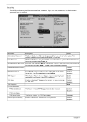
... Password User Password Set Administrator Password Power/Reset Button Lockout BIOS Write Protect TPM Support TPM State TPM Operation Current TPM Status TPM Enabled Status TPM Active Status TPM Owner Status Chassis Opened Warning Description Option This item indicates if an Administrator password has been entered for the system. Enabled Disabled This feature displays the TPM Owner status. "Not Installed" means a Administrator password has not been set . Enabled Disabled TPM (Trusted Platform Module) Support improves data integrity and network security. If you use both passwords...
... Password User Password Set Administrator Password Power/Reset Button Lockout BIOS Write Protect TPM Support TPM State TPM Operation Current TPM Status TPM Enabled Status TPM Active Status TPM Owner Status Chassis Opened Warning Description Option This item indicates if an Administrator password has been entered for the system. Enabled Disabled This feature displays the TPM Owner status. "Not Installed" means a Administrator password has not been set . Enabled Disabled TPM (Trusted Platform Module) Support improves data integrity and network security. If you use both passwords...

Acer AC100 Service Guide
Page 98
... Num-Lock POST Error Pause Option ROM Message Description Enables or disables Quiet Boot option. Disabled Enables or disables the conversion of a duplicate event that must pass between duplicate log entries which utilize a mutliple event counter. Valid entry is updated. Selects the keyboard NumLock state. Do Nothing Erase Immediately Sets the number of occurrences of EFI status codes to access the related submenu screen. Sets the display mode for erasing SMBIOS Event Log. Erasing is...
... Num-Lock POST Error Pause Option ROM Message Description Enables or disables Quiet Boot option. Disabled Enables or disables the conversion of a duplicate event that must pass between duplicate log entries which utilize a mutliple event counter. Valid entry is updated. Selects the keyboard NumLock state. Do Nothing Erase Immediately Sets the number of occurrences of EFI status codes to access the related submenu screen. Sets the display mode for erasing SMBIOS Event Log. Erasing is...
Acer AC100 Service Guide
Page 103
... is bad, update CMOS with power-on CMOS setup questions. Some interrupt vectors are the largest set of checkpoints during the BIOS pre-boot process. Search for pre-defined recovery file name in the Kernel Variable "wCMOSFlags." Start reading the recovery file cluster by reading storage area. Detect proper flash part. Check CMOS diagnostic byte to determine if battery power is OK and CMOS checksum is enabled. Do R/W test to F000 ROM at F000...
... is bad, update CMOS with power-on CMOS setup questions. Some interrupt vectors are the largest set of checkpoints during the BIOS pre-boot process. Search for pre-defined recovery file name in the Kernel Variable "wCMOSFlags." Start reading the recovery file cluster by reading storage area. Detect proper flash part. Check CMOS diagnostic byte to determine if battery power is OK and CMOS checksum is enabled. Do R/W test to F000 ROM at F000...
Acer AC100 Service Guide
Page 104
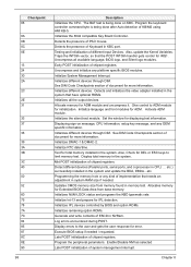
... modules. Testing and initialization of system management interrupt. Detects and initializes the video adapter installed in memory test. Allocate memory for IPL detection. Updates CMOS memory size from base memory. Initializes IPL devices controlled by BIOS and option ROMs. Initializes remaining option ROMs. Generate and write contents of chipset registers. Initializes the 8042 compatible Key Board Controller. Give control to the user and gets the user response for more information. Activate ADM module. Initializes the silent boot module. Mid POST...
... modules. Testing and initialization of system management interrupt. Detects and initializes the video adapter installed in memory test. Allocate memory for IPL detection. Updates CMOS memory size from base memory. Initializes IPL devices controlled by BIOS and option ROMs. Initializes remaining option ROMs. Generate and write contents of chipset registers. Initializes the 8042 compatible Key Board Controller. Give control to the user and gets the user response for more information. Activate ADM module. Initializes the silent boot module. Mid POST...
Acer AC100 Service Guide
Page 106
... port 80h, attempt to port 80h. The following beep codes: • One long and two short beeps - video configuration error • One repetitive long beep - Recoverable POST Errors When a recoverable type of error occurs during warm boot Initialize PCI Bus Mastering devices Initialize keyboard controller 1-2-2-3 BIOS ROM checksum Initialize cache before memory Auto size 8254 timer initialization 8237 DMA controller initialization Reset Programmable Interrupt Controller 100 Chapter 8 no memory detected Terminal POST Errors If a terminal type of the screen. Post Code...
... port 80h, attempt to port 80h. The following beep codes: • One long and two short beeps - video configuration error • One repetitive long beep - Recoverable POST Errors When a recoverable type of error occurs during warm boot Initialize PCI Bus Mastering devices Initialize keyboard controller 1-2-2-3 BIOS ROM checksum Initialize cache before memory Auto size 8254 timer initialization 8237 DMA controller initialization Reset Programmable Interrupt Controller 100 Chapter 8 no memory detected Terminal POST Errors If a terminal type of the screen. Post Code...
Acer AC100 Service Guide
Page 108
... Multi Processor APIC Enable external and CPU caches Setup System Management Mode (SMM) area Display external L2 cache size Load custom defaults (optional) Display shadow-area message Display possible high address for UMB recovery Display error messages Check for configuration errors Check for keyboard errors Set up hardware interrupt vectors Initialize Intelligent System Monitoring Initialize coprocessor if present Disable onboard Super I/O ports and IRQs Late POST device initialization Detect and install external RS232 ports Configure non-MCD IDE controllers Detect and install external...
... Multi Processor APIC Enable external and CPU caches Setup System Management Mode (SMM) area Display external L2 cache size Load custom defaults (optional) Display shadow-area message Display possible high address for UMB recovery Display error messages Check for configuration errors Check for keyboard errors Set up hardware interrupt vectors Initialize Intelligent System Monitoring Initialize coprocessor if present Disable onboard Super I/O ports and IRQs Late POST device initialization Detect and install external RS232 ports Configure non-MCD IDE controllers Detect and install external...

Acer AC100 Service Guide
Page 109
... for multi-processor boards Install CD ROM for boot Clear huge ES segment register 1-2 Search for option ROMs. One long, two short beeps on check-sum failure Check for SMART Drive (optional) Shadow option ROMs Set up Power Management Initialize security engine (optional) Enable hardware interrupts Determine number of ATA and SCSI drives Set time of day Check key lock Initialize typematic rate Erase F2 prompt Scan for F2 key stroke Enter SETUP Clear Boot flag Check for errors Inform RomPilot...
... for multi-processor boards Install CD ROM for boot Clear huge ES segment register 1-2 Search for option ROMs. One long, two short beeps on check-sum failure Check for SMART Drive (optional) Shadow option ROMs Set up Power Management Initialize security engine (optional) Enable hardware interrupts Determine number of ATA and SCSI drives Set time of day Check key lock Initialize typematic rate Erase F2 prompt Scan for F2 key stroke Enter SETUP Clear Boot flag Check for errors Inform RomPilot...
Acer AC100 Service Guide
Page 111
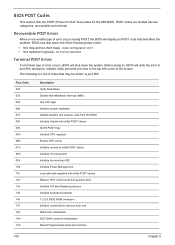
... port-80 LED display. Post Code E7h E8h E9h EAh EBh ECh EDh EEh EFh F0h F1h F2h F3h F4h F5h F6h F7h Description Go to BIOS Set Huge Segment Initialize Multi Processor Initialize OEM special code Initialize PIC and DMA Initialize Memory type Initialize Memory size Shadow Boot Block System memory test Initialize interrupt vectors Initialize Run Time Clock Initialize video Initialize System Management Manager Output one set) has failed...
... port-80 LED display. Post Code E7h E8h E9h EAh EBh ECh EDh EEh EFh F0h F1h F2h F3h F4h F5h F6h F7h Description Go to BIOS Set Huge Segment Initialize Multi Processor Initialize OEM special code Initialize PIC and DMA Initialize Memory type Initialize Memory size Shadow Boot Block System memory test Initialize interrupt vectors Initialize Run Time Clock Initialize video Initialize System Management Manager Output one set) has failed...


