Service Guide
Page 7
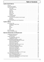
... System Block Diagram 3 Your Acer Notebook tour 4 Front View 4 Closed Front View 5 Left View 5 Right View 6 Rear View 6 Bottom View 7 Indicators 7 TouchPad Basics 8 Using the Keyboard 9 Lock Keys and embedded numeric...26 BIOS Flash Utility 27 Remove HDD/BIOS Utility 29 Machine Disassembly and Replacement 33 Disassembly Requirements 33 Related Information 33 General Information 34 Pre-disassembly Instructions... 35 External Modules Disassembly Flowchart 35 Removing the Battery Pack 36 Removing the 3G Cover 37 Removing the Keyboard 38 Removing the Upper and Lower Covers 39 ...
... System Block Diagram 3 Your Acer Notebook tour 4 Front View 4 Closed Front View 5 Left View 5 Right View 6 Rear View 6 Bottom View 7 Indicators 7 TouchPad Basics 8 Using the Keyboard 9 Lock Keys and embedded numeric...26 BIOS Flash Utility 27 Remove HDD/BIOS Utility 29 Machine Disassembly and Replacement 33 Disassembly Requirements 33 Related Information 33 General Information 34 Pre-disassembly Instructions... 35 External Modules Disassembly Flowchart 35 Removing the Battery Pack 36 Removing the 3G Cover 37 Removing the Keyboard 38 Removing the Upper and Lower Covers 39 ...
Service Guide
Page 8
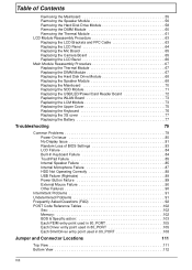
... 67 Replacing the DIMM Module 67 Replacing the Hard Disk Drive Module 68 Replacing the Speaker Module 68 Replacing the Mainboard 70 Replacing the SDD Module 71 Replacing the USB/LED/Power/Card Reader Board 72 Replacing the WLAN Board 73 Replacing the LCM Module 73 Replacing the Upper Cover 75 Replacing the Keyboard 76 Replacing the 3G cover 77 Replacing the Battery 77...
... 67 Replacing the DIMM Module 67 Replacing the Hard Disk Drive Module 68 Replacing the Speaker Module 68 Replacing the Mainboard 70 Replacing the SDD Module 71 Replacing the USB/LED/Power/Card Reader Board 72 Replacing the WLAN Board 73 Replacing the LCM Module 73 Replacing the Upper Cover 75 Replacing the Keyboard 76 Replacing the 3G cover 77 Replacing the Battery 77...

Service Guide
Page 86
Replace keyboard cable to secure in the mounting. 3. Replacing the Keyboard 1. Turn the keyboard over and place the front edge first in place. 76 Chapter 3 Turn the computer upside down on the bottom panel to attach the upper and lower covers. 6. Replace the two rubber foot pads. 5. Press down and replace the eight securing screws on the areas shown below to the mainboard, and secure the locking latch. 2.
Replace keyboard cable to secure in the mounting. 3. Replacing the Keyboard 1. Turn the keyboard over and place the front edge first in place. 76 Chapter 3 Turn the computer upside down on the bottom panel to attach the upper and lower covers. 6. Replace the two rubber foot pads. 5. Press down and replace the eight securing screws on the areas shown below to the mainboard, and secure the locking latch. 2.

Service Guide
Page 94
Do not replace a non-defective FRUs: 84 Chapter 4 Do not replace a nondefective FRUs: Built-In Keyboard Failure If the built-in Keyboard fails, perform the following actions one at a time to correct the problem. LCD Failure If the LCD fails, perform the following actions one at a time to correct the problem.
Do not replace a non-defective FRUs: 84 Chapter 4 Do not replace a nondefective FRUs: Built-In Keyboard Failure If the built-in Keyboard fails, perform the following actions one at a time to correct the problem. LCD Failure If the LCD fails, perform the following actions one at a time to correct the problem.