Service Guide
Page 7
... Diagram 3 Your Acer Notebook tour 4 ...Utility 29 Machine Disassembly and Replacement 33 Disassembly Requirements 33 ...Battery Pack 36 Removing the 3G Cover 37 Removing the Keyboard 38 Removing the Upper and Lower Covers 39 LCD Module Disassembly Process 41 LCD Module Disassembly Flowchart 41 Removing the LCD Module 42 Removing the LCD... Bezel 44 Removing the Camera Board 45 Removing the MIC Board 46 Removing the LCD Panel 47 Removing the LCD Brackets and FPC Cable...
... Diagram 3 Your Acer Notebook tour 4 ...Utility 29 Machine Disassembly and Replacement 33 Disassembly Requirements 33 ...Battery Pack 36 Removing the 3G Cover 37 Removing the Keyboard 38 Removing the Upper and Lower Covers 39 LCD Module Disassembly Process 41 LCD Module Disassembly Flowchart 41 Removing the LCD Module 42 Removing the LCD... Bezel 44 Removing the Camera Board 45 Removing the MIC Board 46 Removing the LCD Panel 47 Removing the LCD Brackets and FPC Cable...
Service Guide
Page 8
... Reassembly Procedure 63 Replacing the LCD Brackets and FPC Cable 63 Replacing the LCD Panel 64 Replacing the Mic Board 65 Replacing the Camera Board 65 Replacing the LCD Bezel 66 Main Module Reassembly Procedure 67 Replacing the Thermal Module 67 Replacing the DIMM Module 67 Replacing the Hard Disk Drive Module 68 Replacing the Speaker Module 68 Replacing the Mainboard 70 Replacing the SDD...
... Reassembly Procedure 63 Replacing the LCD Brackets and FPC Cable 63 Replacing the LCD Panel 64 Replacing the Mic Board 65 Replacing the Camera Board 65 Replacing the LCD Bezel 66 Main Module Reassembly Procedure 67 Replacing the Thermal Module 67 Replacing the DIMM Module 67 Replacing the Hard Disk Drive Module 68 Replacing the Speaker Module 68 Replacing the Mainboard 70 Replacing the SDD...

Service Guide
Page 44
...example, if you want to the system and all power and signal cables from the system. 3. Place the system on a flat, stable ...to remove the main board, you do the following sections: • Upper cover disassembly • LCD module disassembly • Main unit disassembly The flowcharts provided in that you must first remove the ...the inside assembly frame in the succeeding disassembly sections illustrate the entire disassembly sequence. Remove the battery pack. General Information Pre-disassembly Instructions Before proceeding with the disassembly procedure, make sure that...
...example, if you want to the system and all power and signal cables from the system. 3. Place the system on a flat, stable ...to remove the main board, you do the following sections: • Upper cover disassembly • LCD module disassembly • Main unit disassembly The flowcharts provided in that you must first remove the ...the inside assembly frame in the succeeding disassembly sections illustrate the entire disassembly sequence. Remove the battery pack. General Information Pre-disassembly Instructions Before proceeding with the disassembly procedure, make sure that...

Service Guide
Page 52
NOTE: Main cable is white. 42 Chapter 3 Disconnect and remove the antenna cables from its connector 3. The Auxiliary cable is black. See "Removing the Upper and Lower Covers" on page 39. 2. Remove the Upper Cover. Disconnect the LCD cable from the housing well. Removing the LCD Module 1.
NOTE: Main cable is white. 42 Chapter 3 Disconnect and remove the antenna cables from its connector 3. The Auxiliary cable is black. See "Removing the Upper and Lower Covers" on page 39. 2. Remove the Upper Cover. Disconnect the LCD cable from the housing well. Removing the LCD Module 1.

Service Guide
Page 53
4. IMPORTANT:Ensure all cables are clear of the lower cover before removing the LCD module. 6. Chapter 3 43 Step LCD Module Size M2*5 (NL) Quantity 4 Screw Type 5. Tilt the LCD module so it sits at a 90 degree angle. Remove the four securing screws from the hinges. Grasp the module by both sides and lift upwards.
4. IMPORTANT:Ensure all cables are clear of the lower cover before removing the LCD module. 6. Chapter 3 43 Step LCD Module Size M2*5 (NL) Quantity 4 Screw Type 5. Tilt the LCD module so it sits at a 90 degree angle. Remove the four securing screws from the hinges. Grasp the module by both sides and lift upwards.

Service Guide
Page 55
Chapter 3 45 Remove the camera board from its connector as shown. 3. Removing the Camera Board 1. Disconnect the Camera Module cable from the LCD cover. See "Removing the LCD Bezel" on page 44. 2. Remove the LCD Bezel.
Chapter 3 45 Remove the camera board from its connector as shown. 3. Removing the Camera Board 1. Disconnect the Camera Module cable from the LCD cover. See "Removing the LCD Bezel" on page 44. 2. Remove the LCD Bezel.

Service Guide
Page 56
Disconnect the MIC cable from the LCD cover. 46 Chapter 3 Remove the MIC board from its connector as shown. 3. Removing the MIC Board 1. Remove the LCD Bezel. See "Removing the LCD Bezel" on page 44. 2.
Disconnect the MIC cable from the LCD cover. 46 Chapter 3 Remove the MIC board from its connector as shown. 3. Removing the MIC Board 1. Remove the LCD Bezel. See "Removing the LCD Bezel" on page 44. 2.

Service Guide
Page 57
Remove the five (5) securing screws from its housing well. Step LCD Panel Size M2*4 (NL) Quantity 5 4. Grasp the left hinge and pivot down before pulling up. 5. Remove the LCD Bezel. Screw Type Chapter 3 47 Remove it from the LCD Module. Disconnect the MIC cable. See "Removing the LCD Bezel" on page 46. 3. See "Removing the MIC Board" on page 44. 2. Removing the LCD Panel 1.
Remove the five (5) securing screws from its housing well. Step LCD Panel Size M2*4 (NL) Quantity 5 4. Grasp the left hinge and pivot down before pulling up. 5. Remove the LCD Bezel. Screw Type Chapter 3 47 Remove it from the LCD Module. Disconnect the MIC cable. See "Removing the LCD Bezel" on page 46. 3. See "Removing the MIC Board" on page 44. 2. Removing the LCD Panel 1.

Service Guide
Page 58
Hold the LCD Panel from its connector as shown. 48 Chapter 3 See "Removing the LCD Panel" on a clean surface. Disconnect the LCD cable from the sides and lift to remove. Removing the LCD Brackets and FPC Cable 1. Remove the LCD Panel. Turn the LCD panel over on page 47. 2. Place it on a clean surface. 6. Remove the adhesive strips securing the LCD cable. 3.
Hold the LCD Panel from its connector as shown. 48 Chapter 3 See "Removing the LCD Panel" on a clean surface. Disconnect the LCD cable from the sides and lift to remove. Removing the LCD Brackets and FPC Cable 1. Remove the LCD Panel. Turn the LCD panel over on page 47. 2. Place it on a clean surface. 6. Remove the adhesive strips securing the LCD cable. 3.
Service Guide
Page 61
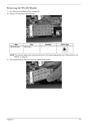
Remove it from the mainboard as shown. See "Removing the LCD Module" on page 36. 2. The module pops up. Remove the securing screw as shown. Chapter 3 51 Removing the WLAN Module 1. See "Removing the Battery Pack" on page 42. 3. Step WLAN Module Size M2*3 (NL) Quantity 1 Screw Type NOTE: The antenna cables were removed during the LCD module disassembly.
Remove it from the mainboard as shown. See "Removing the LCD Module" on page 36. 2. The module pops up. Remove the securing screw as shown. Chapter 3 51 Removing the WLAN Module 1. See "Removing the Battery Pack" on page 42. 3. Step WLAN Module Size M2*3 (NL) Quantity 1 Screw Type NOTE: The antenna cables were removed during the LCD module disassembly.

Service Guide
Page 73
LCD Module Reassembly Procedure Replacing the LCD Brackets and FPC Cable 1. IMPORTANT:The indicator pairs on the brackets must be located diagonally opposite each other. 2. Chapter 3 63 Turn the LCD panel over and connect the FPC cable to the panel. 3. Secure the cable with the adhesive strips as shown. Replace the four LCD brackets as shown.
LCD Module Reassembly Procedure Replacing the LCD Brackets and FPC Cable 1. IMPORTANT:The indicator pairs on the brackets must be located diagonally opposite each other. 2. Chapter 3 63 Turn the LCD panel over and connect the FPC cable to the panel. 3. Secure the cable with the adhesive strips as shown. Replace the four LCD brackets as shown.

Service Guide
Page 74
Place the LCD Panel in to the panel • Check that the cables are tucked under the hinge brackets and run on the outside of the following items: • All cabling must be tucked tightly and close to the case as shown. 2. Replace the left hinge as shown. 64 Chapter 3 Replace the five securing screws as shown. 3. Replacing the LCD Panel IMPORTANT:Before installing, take care of the hinges 1.
Place the LCD Panel in to the panel • Check that the cables are tucked under the hinge brackets and run on the outside of the following items: • All cabling must be tucked tightly and close to the case as shown. 2. Replace the left hinge as shown. 64 Chapter 3 Replace the five securing screws as shown. 3. Replacing the LCD Panel IMPORTANT:Before installing, take care of the hinges 1.

Service Guide
Page 84
Connect the LCD cable to AUX (right). 5. Replace the antenna cables in the housing well, as shown. 4. Replace the two antenna cables. 3. NOTE: The following is the correct cable-color to connector designation: Black to MAIN (left) and White to the mainboard. 74 Chapter 3
Connect the LCD cable to AUX (right). 5. Replace the antenna cables in the housing well, as shown. 4. Replace the two antenna cables. 3. NOTE: The following is the correct cable-color to connector designation: Black to MAIN (left) and White to the mainboard. 74 Chapter 3
Service Guide
Page 92
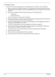
...between the internal display and the external display is done by removing the power cable and battery and holding down the power button for specific model procedures. 2. If the POST or video ...appears on the external display, see "LCD Failure" on page 161. 82 Chapter 4 Disconnect ... computer. No POST or Video If the POST or video doesn't display, perform the following actions one at least one of the following occurs: • Fans start up • Status LEDs light up If there is...
...between the internal display and the external display is done by removing the power cable and battery and holding down the power button for specific model procedures. 2. If the POST or video ...appears on the external display, see "LCD Failure" on page 161. 82 Chapter 4 Disconnect ... computer. No POST or Video If the POST or video doesn't display, perform the following actions one at least one of the following occurs: • Fans start up • Status LEDs light up If there is...
Service Guide
Page 93
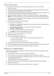
...computer is experiencing intermittent loss of BIOS information, perform the following actions one at a time to correct the problem. 1. If the BIOS settings are no red Xs or yellow exclamation marks. • There are still lost, replace the cables. 4. See "Disassembly Process" on page 34. 5. If display ... 7. Check the Device Manager to determine that the computer is not running on the screen), the LCD is faulty and should be replaced. If the computer is more than one year old, replace the CMOS battery. 2. If the Issue is too dim at a time to correct the problem. 1. See ...
...computer is experiencing intermittent loss of BIOS information, perform the following actions one at a time to correct the problem. 1. If the BIOS settings are no red Xs or yellow exclamation marks. • There are still lost, replace the cables. 4. See "Disassembly Process" on page 34. 5. If display ... 7. Check the Device Manager to determine that the computer is not running on the screen), the LCD is faulty and should be replaced. If the computer is more than one year old, replace the CMOS battery. 2. If the Issue is too dim at a time to correct the problem. 1. See ...

Service Guide
Page 129
LED POWER/B TO MB FFC CABLE - Category Cables Description POWER CORD US 3PIN ROHS POWER CORD PRC 3P Y536B30001218008 POWER CORD(S.A) 1.8M 3BLACK FZ010008-006 ARGENTINE POWER CORD 3 PIN BLACK POWER CORD AU W/... POWER CORD ITALIAN 3PIN POWER CORD JAPAN POWER CORD AF-S (INDIA) POWER CORD SWISS 3 PIN POWER CORD (UK) POWER CORD US-110V (BSMI) CABLE - SSD TO MB LCD CABLE Case/Cover/Bracket/Assembly UPPER CASE ASSY WHITE COLOR W/TP FFC Part No. 27.TAXV7.001 27.TATV7.004 27.T48V7.001 27.S0207...
LED POWER/B TO MB FFC CABLE - Category Cables Description POWER CORD US 3PIN ROHS POWER CORD PRC 3P Y536B30001218008 POWER CORD(S.A) 1.8M 3BLACK FZ010008-006 ARGENTINE POWER CORD 3 PIN BLACK POWER CORD AU W/... POWER CORD ITALIAN 3PIN POWER CORD JAPAN POWER CORD AF-S (INDIA) POWER CORD SWISS 3 PIN POWER CORD (UK) POWER CORD US-110V (BSMI) CABLE - SSD TO MB LCD CABLE Case/Cover/Bracket/Assembly UPPER CASE ASSY WHITE COLOR W/TP FFC Part No. 27.TAXV7.001 27.TATV7.004 27.T48V7.001 27.S0207...