Service Guide
Page 7
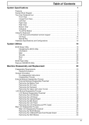
Table of Contents System Specifications 1 Features 1 System Block Diagram 3 Your Acer Notebook tour 4 Front View 4 Closed Front View 5 Left View 5 ... Exit 26 BIOS Flash Utility 27 Remove HDD/BIOS Utility 29 Machine Disassembly and Replacement 33 Disassembly Requirements 33 Related Information 33 General Information 34 Pre-disassembly Instructions 34... Process 34 External Module Disassembly Process 35 External Modules Disassembly Flowchart 35 Removing the Battery Pack 36 Removing the 3G Cover 37 Removing the Keyboard 38 Removing the Upper...52 Removing the SSD Module 53 VII
Table of Contents System Specifications 1 Features 1 System Block Diagram 3 Your Acer Notebook tour 4 Front View 4 Closed Front View 5 Left View 5 ... Exit 26 BIOS Flash Utility 27 Remove HDD/BIOS Utility 29 Machine Disassembly and Replacement 33 Disassembly Requirements 33 Related Information 33 General Information 34 Pre-disassembly Instructions 34... Process 34 External Module Disassembly Process 35 External Modules Disassembly Flowchart 35 Removing the Battery Pack 36 Removing the 3G Cover 37 Removing the Keyboard 38 Removing the Upper...52 Removing the SSD Module 53 VII
Service Guide
Page 11
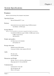
... Windows® XP™ / Linux Platform • Diamondville Atrom series standard voltage 533FSB processors • Intel 945GSE + ICH7M Chipset System Memory NOTE: It is not possible for end users to upgrade the Aspire one memory. • One DDRII SO-DIMM slots support 512MB to 1024MB system memory • 512MB... Internal Digital MIC Dimensions and Weight • 248 (W) x 169.4 (D) x 29.5 (H) mm (ME dimension) • 995g weight with 8.9" LCD and 8GB SSD Communication • On-Board PCI-E 10/100 LAN • Mini-card Wireless LAN • Wake-on-LAN support Chapter 1 Chapter 1 1
... Windows® XP™ / Linux Platform • Diamondville Atrom series standard voltage 533FSB processors • Intel 945GSE + ICH7M Chipset System Memory NOTE: It is not possible for end users to upgrade the Aspire one memory. • One DDRII SO-DIMM slots support 512MB to 1024MB system memory • 512MB... Internal Digital MIC Dimensions and Weight • 248 (W) x 169.4 (D) x 29.5 (H) mm (ME dimension) • 995g weight with 8.9" LCD and 8GB SSD Communication • On-Board PCI-E 10/100 LAN • Mini-card Wireless LAN • Wake-on-LAN support Chapter 1 Chapter 1 1

Service Guide
Page 23
... Item Memory controller Memory size DIMM socket number Supports memory size per socket Supports maximum memory size Supports DIMM type Supports DIMM Speed System Storage SSD Item HDD Specification • FCBGA • Ball Count: 998 balls • Package Size: 27 mm x 27 mm • Ball pitch: 0.8-mm uniform pitch Specification Built...
... Item Memory controller Memory size DIMM socket number Supports memory size per socket Supports maximum memory size Supports DIMM type Supports DIMM Speed System Storage SSD Item HDD Specification • FCBGA • Ball Count: 998 balls • Package Size: 27 mm x 27 mm • Ball pitch: 0.8-mm uniform pitch Specification Built...
Service Guide
Page 43
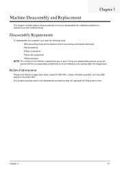
... screws with the corresponding components to disassemble the notebook computer for the different components vary in the disassembly procedures may differ slightly from a SSD SKU. Machine Disassembly and Replacement Chapter 3 This chapter contains step-by-step procedures on how to avoid mismatch when putting back the components. The product previews seen in...
... screws with the corresponding components to disassemble the notebook computer for the different components vary in the disassembly procedures may differ slightly from a SSD SKU. Machine Disassembly and Replacement Chapter 3 This chapter contains step-by-step procedures on how to avoid mismatch when putting back the components. The product previews seen in...
Service Guide
Page 60
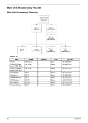
Main Unit Disassembly Process Main Unit Disassembly Flowchart Screw List Step WLAN USB/LED/Power Board (HDD SKU) USB/LED/Power Board (SSD SKU) SSD Module Mainboard Speaker Module HDD Module HDD Carrier Thermal Module Screw M2*3 (NL) M2*3 (NL) M2*3 (NL) M2*3 M2*3 M2*3 M2.5*4 M3*3.5 M2*3 Quantity 1 3 4 2 1 4 2 4 3 Color Black Black Black Black Black Black Black Black Black Part No. 86.S0207.001 86.S0207.001 86.S0207.001 86.S0207.001 86.S0207.001 86.S0207.001 86.D01V7.001 86.TDY07.003 86.S0207.001 50 Chapter 3
Main Unit Disassembly Process Main Unit Disassembly Flowchart Screw List Step WLAN USB/LED/Power Board (HDD SKU) USB/LED/Power Board (SSD SKU) SSD Module Mainboard Speaker Module HDD Module HDD Carrier Thermal Module Screw M2*3 (NL) M2*3 (NL) M2*3 (NL) M2*3 M2*3 M2*3 M2.5*4 M3*3.5 M2*3 Quantity 1 3 4 2 1 4 2 4 3 Color Black Black Black Black Black Black Black Black Black Part No. 86.S0207.001 86.S0207.001 86.S0207.001 86.S0207.001 86.S0207.001 86.S0207.001 86.D01V7.001 86.TDY07.003 86.S0207.001 50 Chapter 3
Service Guide
Page 62
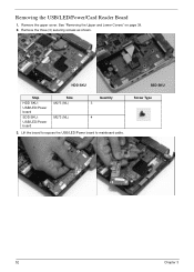
Remove the three (3) securing screws as shown. Lift the board to expose the USB/LED/Power board to mainboard cable. Removing the USB/LED/Power/Card Reader Board 1. See "Removing the Upper and Lower Covers" on page 39. 2. HDD SKU SSD SKU Step HDD SKU: USB/LED/Power board SDD SKU: USB/LED/Power board Size M2*3 (NL) M2*3 (NL) Quantity 3 4 3. Screw Type 52 Chapter 3 Remove the upper cover.
Remove the three (3) securing screws as shown. Lift the board to expose the USB/LED/Power board to mainboard cable. Removing the USB/LED/Power/Card Reader Board 1. See "Removing the Upper and Lower Covers" on page 39. 2. HDD SKU SSD SKU Step HDD SKU: USB/LED/Power board SDD SKU: USB/LED/Power board Size M2*3 (NL) M2*3 (NL) Quantity 3 4 3. Screw Type 52 Chapter 3 Remove the upper cover.
Service Guide
Page 63
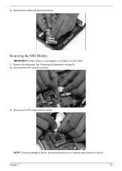
Disconnect the FFC cable from its connector. 3. Removing the SSD Module IMPORTANT:The SSD module is only available on page 55. 2. See "Removing the Mainboard" on the Aspire one SSD SKU. 1. NOTE: To prevent damage to device, avoid pressing down on it or placing heavy objects on top of it. Disconnect the FFC from the module. Remove the mainboard. Chapter 3 53 Disconnect the cable and remove the board. 4.
Disconnect the FFC cable from its connector. 3. Removing the SSD Module IMPORTANT:The SSD module is only available on page 55. 2. See "Removing the Mainboard" on the Aspire one SSD SKU. 1. NOTE: To prevent damage to device, avoid pressing down on it or placing heavy objects on top of it. Disconnect the FFC from the module. Remove the mainboard. Chapter 3 53 Disconnect the cable and remove the board. 4.

Service Guide
Page 64
Quantity 2 Screw Type 54 Chapter 3 4. Remove the two securing screws. Step SSD Module Size M2*3 (NL) 5. Remove the SSD module.
Quantity 2 Screw Type 54 Chapter 3 4. Remove the two securing screws. Step SSD Module Size M2*3 (NL) 5. Remove the SSD module.

Service Guide
Page 66
Removing the Speaker Module 1. NOTE: The SSD image may differ from the following illustration. 6. Peel back the two adhesive strips. 56 Chapter 3 Grip the mainboard and remove. Remove the Upper Cover. See "Removing the Upper and Lower Covers" on page 39. 2.
Removing the Speaker Module 1. NOTE: The SSD image may differ from the following illustration. 6. Peel back the two adhesive strips. 56 Chapter 3 Grip the mainboard and remove. Remove the Upper Cover. See "Removing the Upper and Lower Covers" on page 39. 2.
Service Guide
Page 70
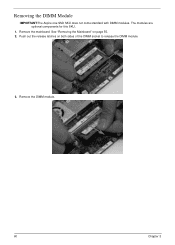
Push out the release latches on page 55. 2. Remove the DIMM module. 60 Chapter 3 See "Removing the Mainboard" on both sides of the DIMM socket to release the DIMM module. 3. The modules are optional components for this SKU. 1. Removing the DIMM Module IMPORTANT:The Aspire one SSD SKU does not come standard with DIMM modules. Remove the mainboard.
Push out the release latches on page 55. 2. Remove the DIMM module. 60 Chapter 3 See "Removing the Mainboard" on both sides of the DIMM socket to release the DIMM module. 3. The modules are optional components for this SKU. 1. Removing the DIMM Module IMPORTANT:The Aspire one SSD SKU does not come standard with DIMM modules. Remove the mainboard.
Service Guide
Page 77
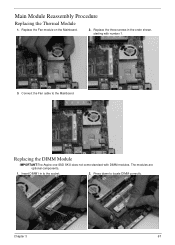
Replacing the DIMM Module IMPORTANT:The Aspire one SSD SKU does not come standard with number 1. 3. Insert DIMM1 in the order shown, starting with DIMM modules. Press down to the Mainboard. Connect the Fan cable to locate DIMM correctly. Main Module Reassembly Procedure Replacing the Thermal Module 1. Replace the Fan module on the Mainboard. 2. The modules are optional components. 1. Chapter 3 67 Replace the three screws in to the socket. 2.
Replacing the DIMM Module IMPORTANT:The Aspire one SSD SKU does not come standard with number 1. 3. Insert DIMM1 in the order shown, starting with DIMM modules. Press down to the Mainboard. Connect the Fan cable to locate DIMM correctly. Main Module Reassembly Procedure Replacing the Thermal Module 1. Replace the Fan module on the Mainboard. 2. The modules are optional components. 1. Chapter 3 67 Replace the three screws in to the socket. 2.
Service Guide
Page 81
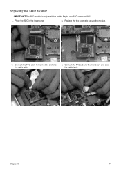
Connect the FFC cable to secure the module. 3. Chapter 3 71 Replace the two screws to the module and close the cable latch. Connect the FFC cable to the mainboard and close 4. the cable latch. Replacing the SDD Module IMPORTANT:The SSD module is only available on the Aspire one SSD computer SKU. 1. Place the SDD in the lower case. 2.
Connect the FFC cable to secure the module. 3. Chapter 3 71 Replace the two screws to the module and close the cable latch. Connect the FFC cable to the mainboard and close 4. the cable latch. Replacing the SDD Module IMPORTANT:The SSD module is only available on the Aspire one SSD computer SKU. 1. Place the SDD in the lower case. 2.
Service Guide
Page 82
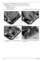
Replacing the USB/LED/Power/Card Reader Board IMPORTANT:Before installing the USB board, take care of the following items: • Check that LED isn`t broken • SLIDER work smoothly 1. Connect the FFC cable to the module and close the cable latch. the cable latch. 72 Chapter 3 HDD SKU SSD SKU 4. Connect the FFC cable to the mainboard and close 5. Replace the three or four screws (depending on SKU) to the board. 2. Connect the cable to secure the module. Turn the board over and place it in the lower case. 3.
Replacing the USB/LED/Power/Card Reader Board IMPORTANT:Before installing the USB board, take care of the following items: • Check that LED isn`t broken • SLIDER work smoothly 1. Connect the FFC cable to the module and close the cable latch. the cable latch. 72 Chapter 3 HDD SKU SSD SKU 4. Connect the FFC cable to the mainboard and close 5. Replace the three or four screws (depending on SKU) to the board. 2. Connect the cable to secure the module. Turn the board over and place it in the lower case. 3.

Service Guide
Page 129
...-038 POWER CORD ITALIAN 3PIN POWER CORD JAPAN POWER CORD AF-S (INDIA) POWER CORD SWISS 3 PIN POWER CORD (UK) POWER CORD US-110V (BSMI) CABLE - SSD TO MB LCD CABLE Case/Cover/Bracket/Assembly UPPER CASE ASSY WHITE COLOR W/TP FFC Part No. 27.TAXV7.001 27.TATV7.004 27.T48V7...
...-038 POWER CORD ITALIAN 3PIN POWER CORD JAPAN POWER CORD AF-S (INDIA) POWER CORD SWISS 3 PIN POWER CORD (UK) POWER CORD US-110V (BSMI) CABLE - SSD TO MB LCD CABLE Case/Cover/Bracket/Assembly UPPER CASE ASSY WHITE COLOR W/TP FFC Part No. 27.TAXV7.001 27.TATV7.004 27.T48V7...
Service Guide
Page 135
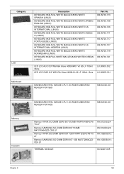
... LCD CMO 8.9" WSVGA Glare N089L6-L02 LF 180nit 16ms LK.08905.002 LK.0890D.001 MAINBOARD INTEL 945GSE CPU 1.6G RAM 512MB W/SD READER FOR SSD MB.S0306.001 Memory Heatsink MAINBOARD INTEL 945GSE CPU 1.6G RAM 512MB W/SD READER FOR HDD MB.S0506.001 Memory HYNIX SO-DIMM DDRII 667...
... LCD CMO 8.9" WSVGA Glare N089L6-L02 LF 180nit 16ms LK.08905.002 LK.0890D.001 MAINBOARD INTEL 945GSE CPU 1.6G RAM 512MB W/SD READER FOR SSD MB.S0306.001 Memory Heatsink MAINBOARD INTEL 945GSE CPU 1.6G RAM 512MB W/SD READER FOR HDD MB.S0506.001 Memory HYNIX SO-DIMM DDRII 667...
