Service Guide
Page 7
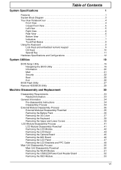
... of Contents System Specifications 1 Features 1 System Block Diagram 3 Your Acer Notebook tour 4 Front View 4 Closed Front View 5 Left View ...Exit 26 BIOS Flash Utility 27 Remove HDD/BIOS Utility 29 Machine Disassembly and Replacement 33 Disassembly Requirements 33 Related Information 33 General Information 34 Pre-disassembly Instructions ...Process 34 External Module Disassembly Process 35 External Modules Disassembly Flowchart 35 Removing the Battery Pack 36 Removing the 3G Cover 37 Removing the Keyboard 38 Removing the ...Reader Board 52 Removing the SSD Module 53 VII
... of Contents System Specifications 1 Features 1 System Block Diagram 3 Your Acer Notebook tour 4 Front View 4 Closed Front View 5 Left View ...Exit 26 BIOS Flash Utility 27 Remove HDD/BIOS Utility 29 Machine Disassembly and Replacement 33 Disassembly Requirements 33 Related Information 33 General Information 34 Pre-disassembly Instructions ...Process 34 External Module Disassembly Process 35 External Modules Disassembly Flowchart 35 Removing the Battery Pack 36 Removing the 3G Cover 37 Removing the Keyboard 38 Removing the ...Reader Board 52 Removing the SSD Module 53 VII
Service Guide
Page 62
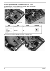
Remove the upper cover. See "Removing the Upper and Lower Covers" on page 39. 2. Screw Type 52 Chapter 3 HDD SKU SSD SKU Step HDD SKU: USB/LED/Power board SDD SKU: USB/LED/Power board Size M2*3 (NL) M2*3 (NL) Quantity 3 4 3. Lift the board to expose the USB/LED/Power board to mainboard cable. Remove the three (3) securing screws as shown. Removing the USB/LED/Power/Card Reader Board 1.
Remove the upper cover. See "Removing the Upper and Lower Covers" on page 39. 2. Screw Type 52 Chapter 3 HDD SKU SSD SKU Step HDD SKU: USB/LED/Power board SDD SKU: USB/LED/Power board Size M2*3 (NL) M2*3 (NL) Quantity 3 4 3. Lift the board to expose the USB/LED/Power board to mainboard cable. Remove the three (3) securing screws as shown. Removing the USB/LED/Power/Card Reader Board 1.

Service Guide
Page 65
Remove the Upper Cover. Remove the single securing screw. Step Mainboard Size M2*3 (NL) Quantity 1 Screw Type Chapter 3 55 Remove the USB/LED/Power/Card Reader Board. Disconnect the speaker to mainboard cable. 5. See "Removing the Upper and Lower Covers" on page 52. 4. See "Removing the USB/LED/Power/Card Reader Board" on page 39. 2. Remove the WLAN module. See "Removing the WLAN Module" on page 51. 3. Removing the Mainboard 1.
Remove the Upper Cover. Remove the single securing screw. Step Mainboard Size M2*3 (NL) Quantity 1 Screw Type Chapter 3 55 Remove the USB/LED/Power/Card Reader Board. Disconnect the speaker to mainboard cable. 5. See "Removing the Upper and Lower Covers" on page 52. 4. See "Removing the USB/LED/Power/Card Reader Board" on page 39. 2. Remove the WLAN module. See "Removing the WLAN Module" on page 51. 3. Removing the Mainboard 1.