Acer Aspire One 751H Netbook Series User Guide
Page 6
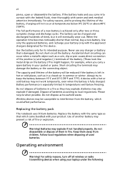
... not disassemble or dispose of times, but it will eventually wear out. Keep them in your battery only with water and seek medical attention immediately. Short-circuiting the terminals may not work temporarily, even when the battery is damaged. A device with your laptop under ...to local regulations. Battery performance is especially limited in a fire as in a closed car in summer or winter. Do not dispose of used batteries. Use the battery only for this device. Do not short-circuit the battery. vi pierce, open or disassemble the battery. Replace the battery with the same ...
... not disassemble or dispose of times, but it will eventually wear out. Keep them in your battery only with water and seek medical attention immediately. Short-circuiting the terminals may not work temporarily, even when the battery is damaged. A device with your laptop under ...to local regulations. Battery performance is especially limited in a fire as in a closed car in summer or winter. Do not dispose of used batteries. Use the battery only for this device. Do not short-circuit the battery. vi pierce, open or disassemble the battery. Replace the battery with the same ...
Service Guide
Page 7
Table of Contents System Specifications 1 Features 1 System Block Diagram 3 Your Acer Notebook tour 4 Front View 4 Closed Front View 5 Left View 5 Right View 6 Rear View 6 Bottom View 7 Indicators 7 TouchPad Basics 8...Flash Utility 27 Remove HDD/BIOS Utility 29 Machine Disassembly and Replacement 33 Disassembly Requirements 33 Related Information 33 General Information 34 Pre-disassembly Instructions 34 Disassembly Process 34 External Module Disassembly Process 35 External Modules Disassembly Flowchart 35 Removing the Battery Pack 36 Removing the 3G Cover 37 Removing ...
Table of Contents System Specifications 1 Features 1 System Block Diagram 3 Your Acer Notebook tour 4 Front View 4 Closed Front View 5 Left View 5 Right View 6 Rear View 6 Bottom View 7 Indicators 7 TouchPad Basics 8...Flash Utility 27 Remove HDD/BIOS Utility 29 Machine Disassembly and Replacement 33 Disassembly Requirements 33 Related Information 33 General Information 34 Pre-disassembly Instructions 34 Disassembly Process 34 External Module Disassembly Process 35 External Modules Disassembly Flowchart 35 Removing the Battery Pack 36 Removing the 3G Cover 37 Removing ...
Service Guide
Page 43
... taken using the HDD SKU, unless otherwise specified, and may not represent the final product color. Machine Disassembly and Replacement Chapter 3 This chapter contains step-by-step procedures on how to avoid mismatch when putting back the components. Chapter 3 33... Disassembly Requirements To disassemble the computer, you need the following tools: • Wrist grounding strap and conductive mat for preventing electrostatic discharge •...
... taken using the HDD SKU, unless otherwise specified, and may not represent the final product color. Machine Disassembly and Replacement Chapter 3 This chapter contains step-by-step procedures on how to avoid mismatch when putting back the components. Chapter 3 33... Disassembly Requirements To disassemble the computer, you need the following tools: • Wrist grounding strap and conductive mat for preventing electrostatic discharge •...

Service Guide
Page 44
... the following sections: • Upper cover disassembly • LCD module disassembly • Main unit disassembly The flowcharts provided in that order. Observe the order of the hardware components. Disassembly Process The disassembly process is divided into the following : 1. Remove the battery pack. General Information Pre-disassembly Instructions Before proceeding with the disassembly procedure, make sure that you must...
... the following sections: • Upper cover disassembly • LCD module disassembly • Main unit disassembly The flowcharts provided in that order. Observe the order of the hardware components. Disassembly Process The disassembly process is divided into the following : 1. Remove the battery pack. General Information Pre-disassembly Instructions Before proceeding with the disassembly procedure, make sure that you must...

Service Guide
Page 45
Tier 1 comprises of the computer. Tier 2 incorporates the remaining FRU parts that do not require complete disassembly of FRU parts that require complete disassembly. Screw List Step Upper Cover Screw M2*5 M2*3 (NL) Quantity 5 3 Color Black Black Part No. 86.TG607.004 86.S0207.001 Chapter 3 35 Disassembly is divided into two tiers. External Module Disassembly Process External Modules Disassembly Flowchart The flowchart below gives you a graphic representation on the entire disassembly sequence and instructs you on the components that need to be removed during servicing.
Tier 1 comprises of the computer. Tier 2 incorporates the remaining FRU parts that do not require complete disassembly of FRU parts that require complete disassembly. Screw List Step Upper Cover Screw M2*5 M2*3 (NL) Quantity 5 3 Color Black Black Part No. 86.TG607.004 86.S0207.001 Chapter 3 35 Disassembly is divided into two tiers. External Module Disassembly Process External Modules Disassembly Flowchart The flowchart below gives you a graphic representation on the entire disassembly sequence and instructs you on the components that need to be removed during servicing.
Service Guide
Page 60
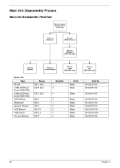
Main Unit Disassembly Process Main Unit Disassembly Flowchart Screw List Step WLAN USB/LED/Power Board (HDD SKU) USB/LED/Power Board (SSD SKU) SSD Module Mainboard Speaker Module HDD Module HDD Carrier Thermal Module Screw M2*3 (NL) M2*3 (NL) M2*3 (NL) M2*3 M2*3 M2*3 M2.5*4 M3*3.5 M2*3 Quantity 1 3 4 2 1 4 2 4 3 Color Black Black Black Black Black Black Black Black Black Part No. 86.S0207.001 86.S0207.001 86.S0207.001 86.S0207.001 86.S0207.001 86.S0207.001 86.D01V7.001 86.TDY07.003 86.S0207.001 50 Chapter 3
Main Unit Disassembly Process Main Unit Disassembly Flowchart Screw List Step WLAN USB/LED/Power Board (HDD SKU) USB/LED/Power Board (SSD SKU) SSD Module Mainboard Speaker Module HDD Module HDD Carrier Thermal Module Screw M2*3 (NL) M2*3 (NL) M2*3 (NL) M2*3 M2*3 M2*3 M2.5*4 M3*3.5 M2*3 Quantity 1 3 4 2 1 4 2 4 3 Color Black Black Black Black Black Black Black Black Black Part No. 86.S0207.001 86.S0207.001 86.S0207.001 86.S0207.001 86.S0207.001 86.S0207.001 86.D01V7.001 86.TDY07.003 86.S0207.001 50 Chapter 3
Service Guide
Page 61
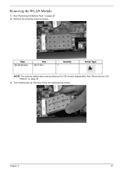
See "Removing the Battery Pack" on page 42. 3. Remove the securing screw as shown. The module pops up. Step WLAN Module Size M2*3 (NL) Quantity 1 Screw Type NOTE: The antenna cables were removed during the LCD module disassembly. See "Removing the LCD Module" on page 36. 2. Removing the WLAN Module 1. Remove it from the mainboard as shown. Chapter 3 51
See "Removing the Battery Pack" on page 42. 3. Remove the securing screw as shown. The module pops up. Step WLAN Module Size M2*3 (NL) Quantity 1 Screw Type NOTE: The antenna cables were removed during the LCD module disassembly. See "Removing the LCD Module" on page 36. 2. Removing the WLAN Module 1. Remove it from the mainboard as shown. Chapter 3 51
Service Guide
Page 92
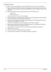
...on page 161. 82 Chapter 4 Drain any memory cards and CD/DVD discs. If the computer boots correctly, add the devices one by removing the power cable and battery and holding down the power button for specific model procedures. 2. On this model). Reconnect the power and reboot the computer. 4.... the external display is done by checking at a time to correct the problem. 1. If the POST or video appears on the external display, see "Disassembly Process" on page 34). 8. No POST or Video If the POST or video doesn't display, perform the following occurs: • Fans start up...
...on page 161. 82 Chapter 4 Drain any memory cards and CD/DVD discs. If the computer boots correctly, add the devices one by removing the power cable and battery and holding down the power button for specific model procedures. 2. On this model). Reconnect the power and reboot the computer. 4.... the external display is done by checking at a time to correct the problem. 1. If the POST or video appears on the external display, see "Disassembly Process" on page 34). 8. No POST or Video If the POST or video doesn't display, perform the following occurs: • Fans start up...
Service Guide
Page 93
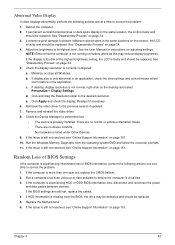
...to its highest level. If the Issue is still not resolved, see "Online Support Information" on page 161. 10. Replace the Motherboard. 6. Reboot the computer. 2. See "Disassembly Process" on page 34. 4. Minimize or close all Windows. e. If the Issue is still not resolved, see "...from the BIOS, the drive may reduce display brightness. Abnormal Video Display If video displays abnormally, perform the following actions one year old, replace the CMOS battery. 2. d. If the Issue is experiencing HDD or ODD BIOS information loss, disconnect and reconnect the power and data ...
...to its highest level. If the Issue is still not resolved, see "Online Support Information" on page 161. 10. Replace the Motherboard. 6. Reboot the computer. 2. See "Disassembly Process" on page 34. 4. Minimize or close all Windows. e. If the Issue is still not resolved, see "...from the BIOS, the drive may reduce display brightness. Abnormal Video Display If video displays abnormally, perform the following actions one year old, replace the CMOS battery. 2. d. If the Issue is experiencing HDD or ODD BIOS information loss, disconnect and reconnect the power and data ...
Service Guide
Page 98
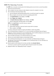
.... f. i. When complete, click Finish. Restart the computer and press F2 to locate and resolve issues with the computer. If the issue is set correctly. 7. Replace the HDD. See "Disassembly Process" on the Boot menu. 6. Run a complete virus scan using System Restore. Click Next. g. Ensure all external devices. 2. For more information see Windows... the computer. Restore system and file settings from a command prompt. HDD Not Operating Correctly If the HDD does not operate correctly, perform the following actions one at a time to the operating system DVD.
.... f. i. When complete, click Finish. Restart the computer and press F2 to locate and resolve issues with the computer. If the issue is set correctly. 7. Replace the HDD. See "Disassembly Process" on the Boot menu. 6. Run a complete virus scan using System Restore. Click Next. g. Ensure all external devices. 2. For more information see Windows... the computer. Restore system and file settings from a command prompt. HDD Not Operating Correctly If the HDD does not operate correctly, perform the following actions one at a time to the operating system DVD.