Aspire 5515 Quick Guide - EN
Page 9
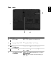
9 Base view English # Icon Item 1 Battery bay Description Houses the computer's battery pack. 2 Battery release latch Releases the battery for removal. 3 Memory compartment Houses the computer's main memory. 4 Hard disk bay Houses the computer's hard disk (secured with screws). 5 Ventilation slots and Enable the computer to stay cool, even after cooling fan prolonged use. Note: Do not cover or obstruct the opening of the fan.
9 Base view English # Icon Item 1 Battery bay Description Houses the computer's battery pack. 2 Battery release latch Releases the battery for removal. 3 Memory compartment Houses the computer's main memory. 4 Hard disk bay Houses the computer's hard disk (secured with screws). 5 Ventilation slots and Enable the computer to stay cool, even after cooling fan prolonged use. Note: Do not cover or obstruct the opening of the fan.
Aspire 5515 Quick Guide - EN
Page 10
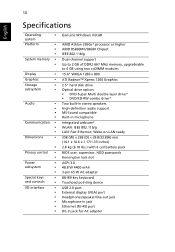
10 English Specifications Operating • system Platform • • • System memory • • Display • Graphics • Storage • subsystem • Audio • • • • Communication • • • Dimensions •...• • • • • • Genuine Windows Vista® AMD Athlon 2650e* processor or higher AMD RS690MC/SB600 Chipset IEEE 802.11b/g Dual-channel support Up to 2 GB of DDR2 667 MHz memory, upgradeable to 4 GB using two soDIMM modules 15.4" WXGA 1280 x 800 ATI Radeon™...
10 English Specifications Operating • system Platform • • • System memory • • Display • Graphics • Storage • subsystem • Audio • • • • Communication • • • Dimensions •...• • • • • • Genuine Windows Vista® AMD Athlon 2650e* processor or higher AMD RS690MC/SB600 Chipset IEEE 802.11b/g Dual-channel support Up to 2 GB of DDR2 667 MHz memory, upgradeable to 4 GB using two soDIMM modules 15.4" WXGA 1280 x 800 ATI Radeon™...
Service Guide
Page 5
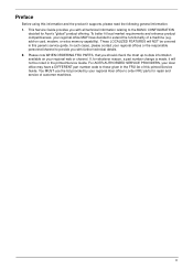
add-on your regional web or channel. In such cases, please contact your regional Acer office to -date information available on card, modem, or extra memory capability). If, for Acer's "global" product offering. Preface Before using this information and the product it will NOT ...BASIC CONFIGURATION decided for whatever reason, a part number change is made, it supports, please read the following general information. 1. For ACER-AUTHORIZED SERVICE PROVIDERS, your regional office MAY have a DIFFERENT part number code to provide you with further technical details. 2. These LOCALIZED...
add-on your regional web or channel. In such cases, please contact your regional Acer office to -date information available on card, modem, or extra memory capability). If, for Acer's "global" product offering. Preface Before using this information and the product it will NOT ...BASIC CONFIGURATION decided for whatever reason, a part number change is made, it supports, please read the following general information. 1. For ACER-AUTHORIZED SERVICE PROVIDERS, your regional office MAY have a DIFFERENT part number code to provide you with further technical details. 2. These LOCALIZED...

Service Guide
Page 11
System Specifications Features Below is a brief summary of the computer's many features: Operating System • Genuine Windows® Vista™ Platform • System Memory • Display and graphics • Storage subsystem • Audio • Dimensions and Weight • Communication • Privacy control • Power subsystem • Special keys and controls • Chapter 1 Chapter 1 1
System Specifications Features Below is a brief summary of the computer's many features: Operating System • Genuine Windows® Vista™ Platform • System Memory • Display and graphics • Storage subsystem • Audio • Dimensions and Weight • Communication • Privacy control • Power subsystem • Special keys and controls • Chapter 1 Chapter 1 1

Service Guide
Page 18
Houses the computer's hard disk (secured with screws). Locks the battery in position. Enable the computer to stay cool, even after prolonged use. Bottom View No. 1 2 3 4 5 6 Icon Item Battery bay Battery release latch Memory compartment Hard disk bay Battery lock Ventilation slots and cooling fan Description Houses the computer's battery pack. Releases the battery for removal. Houses the computer's main memory. Note: Do not cover or obstruct the opening of the fan. 8 Chapter 1
Houses the computer's hard disk (secured with screws). Locks the battery in position. Enable the computer to stay cool, even after prolonged use. Bottom View No. 1 2 3 4 5 6 Icon Item Battery bay Battery release latch Memory compartment Hard disk bay Battery lock Ventilation slots and cooling fan Description Houses the computer's battery pack. Releases the battery for removal. Houses the computer's main memory. Note: Do not cover or obstruct the opening of the fan. 8 Chapter 1

Service Guide
Page 27
...Chapter 1 17 On above table, the configuration of slot 1 and slot 2 could be reversed. System Memory Item Memory controller Memory size DIMM socket number Supports memory size per socket Supports maximum memory size Supports DIMM type Supports DIMM Speed Supports DIMM voltage Cache Features Specification On Board 0 MB 2 2...GB 4 GB DDR SODIMM DDR II 667/800 SDRAM +1.8V 512KB cache on CPU Adjustable 64/128/256MB UMA VGA memory share from North Bridge Memory Combinations Slot 1 0MB 0MB 0MB 512MB 512MB 512MB 1024MB 1024MB 1024MB 1024MB 2048MB 2048MB 2048MB 2048MB 512MB 1024MB 2048MB 512MB ...
...Chapter 1 17 On above table, the configuration of slot 1 and slot 2 could be reversed. System Memory Item Memory controller Memory size DIMM socket number Supports memory size per socket Supports maximum memory size Supports DIMM type Supports DIMM Speed Supports DIMM voltage Cache Features Specification On Board 0 MB 2 2...GB 4 GB DDR SODIMM DDR II 667/800 SDRAM +1.8V 512KB cache on CPU Adjustable 64/128/256MB UMA VGA memory share from North Bridge Memory Combinations Slot 1 0MB 0MB 0MB 512MB 512MB 512MB 1024MB 1024MB 1024MB 1024MB 2048MB 2048MB 2048MB 2048MB 512MB 1024MB 2048MB 512MB ...

Service Guide
Page 29
... Digi/TS-L633A Performance Specification With CD Diskette With DVD Diskette Transfer rate (MB/sec) Sustained: Max 3.5 Mbytes/sec Sustained: Max 10 Mbytes/sec Buffer Memory 2MB Interface SATA Applicable disc format Applicable media types: Writing: Confirms to DVD+R Version 1.2 and DVD+RW Version 1.3 / DVD+R DL Version 1.0 /DVD-R Version 2.0 / DVD-RW...
... Digi/TS-L633A Performance Specification With CD Diskette With DVD Diskette Transfer rate (MB/sec) Sustained: Max 3.5 Mbytes/sec Sustained: Max 10 Mbytes/sec Buffer Memory 2MB Interface SATA Applicable disc format Applicable media types: Writing: Confirms to DVD+R Version 1.2 and DVD+RW Version 1.3 / DVD+R DL Version 1.0 /DVD-R Version 2.0 / DVD-RW...

Service Guide
Page 34
...SelectXSub-Menu F10 Save and Exit NOTE: The screen above is for your reference only. Parameter System Time System Date System Memory Extended Memory Video Memory Quiet Boot Network Boot D2D Recovery SATA Mode Description Sets the system time. Main The Main screen allows the user to ...factory defaults. Information Main System Time: System Date: System Memory: Extended Memory: Video Memory: PhoenixBIOS Setup Utility Advanced Security Power Boot [17:02:07] [09/09/2008] 633 KB 1789 MB [256MB] Exit Item Specific...
...SelectXSub-Menu F10 Save and Exit NOTE: The screen above is for your reference only. Parameter System Time System Date System Memory Extended Memory Video Memory Quiet Boot Network Boot D2D Recovery SATA Mode Description Sets the system time. Main The Main screen allows the user to ...factory defaults. Information Main System Time: System Date: System Memory: Extended Memory: Video Memory: PhoenixBIOS Setup Utility Advanced Security Power Boot [17:02:07] [09/09/2008] 633 KB 1789 MB [256MB] Exit Item Specific...

Service Guide
Page 43
BIOS Flash Utilities The BIOS flash memory update is not completely loaded. NOTE: If you do not have a crisis recovery diskette at hand, then you should create a Crisis Recovery Diskette before you ...use the Phlash utility. Fellow the steps below to finish BIOS flash, you run the Phlash. 1. NOTE: Do not install memory-related drivers (XMS, EMS, DPMI) when you use the Phlash. Then boot the system from the bootable diskette. NOTE: Please use the AC adaptor power...
BIOS Flash Utilities The BIOS flash memory update is not completely loaded. NOTE: If you do not have a crisis recovery diskette at hand, then you should create a Crisis Recovery Diskette before you ...use the Phlash utility. Fellow the steps below to finish BIOS flash, you run the Phlash. 1. NOTE: Do not install memory-related drivers (XMS, EMS, DPMI) when you use the Phlash. Then boot the system from the bootable diskette. NOTE: Please use the AC adaptor power...

Service Guide
Page 54
... Lower Covers Rem ove ODD Rem ove DIMMs Rem ove WLAN Rem ove HDD Rem ove CPU Fan Rem ove Thermal Module Screw List Step Memory Cover HDD Cover ODD Module ODD Bracket WLAN Module HDD Carrier CPU Fan Thermal Module Screw M2.5*10 M2.5*10 M2*3 M2*2.5 M2*3 M3*3 M2...
... Lower Covers Rem ove ODD Rem ove DIMMs Rem ove WLAN Rem ove HDD Rem ove CPU Fan Rem ove Thermal Module Screw List Step Memory Cover HDD Cover ODD Module ODD Bracket WLAN Module HDD Carrier CPU Fan Thermal Module Screw M2.5*10 M2.5*10 M2*3 M2*2.5 M2*3 M3*3 M2...

Service Guide
Page 55
See "Removing the Battery Pack" on page 44. 2. Remove the six screws from the main unit (2). 2 1 Removing the Lower Covers 1. Removing the Battery Pack 1. Step Memory Cover Size M2.5*10 HDD Cover M2.5*10 Quantity 4 2 Memory Cover HDD Cover Screw Type 44 Chapter 3 Turn computer over. 2. Slide and hold the battery release latch to the release position (1), then lift out the battery pack from the memory and HDD covers.
See "Removing the Battery Pack" on page 44. 2. Remove the six screws from the main unit (2). 2 1 Removing the Lower Covers 1. Removing the Battery Pack 1. Step Memory Cover Size M2.5*10 HDD Cover M2.5*10 Quantity 4 2 Memory Cover HDD Cover Screw Type 44 Chapter 3 Turn computer over. 2. Slide and hold the battery release latch to the release position (1), then lift out the battery pack from the memory and HDD covers.

Service Guide
Page 56
Carefully open the memory cover. 4. Remove the HDD cover as shown. Chapter 3 45 3.
Carefully open the memory cover. 4. Remove the HDD cover as shown. Chapter 3 45 3.

Service Guide
Page 60
Remove the Memory Module cover See "Removing the Lower Covers" on page 44. 2. See "Removing the Battery Pack" on page 44. 3. Push out the release latches on both sides of the DIMM socket to release the DIMM module. 4. Chapter 3 49 Removing the DIMM Modules 1. Remove the DIMM module. 5. Repeat steps for the second DIMM module if present.
Remove the Memory Module cover See "Removing the Lower Covers" on page 44. 2. See "Removing the Battery Pack" on page 44. 3. Push out the release latches on both sides of the DIMM socket to release the DIMM module. 4. Chapter 3 49 Removing the DIMM Modules 1. Remove the DIMM module. 5. Repeat steps for the second DIMM module if present.

Service Guide
Page 61
See "Removing the Battery Pack" on page 44. 3. Move the antenna away and remove the two screws on the WLAN board to expose the WLAN board as shown. 4. Remove the Memory cover. See "Removing the Lower Covers" on page 44. 2. Step WLAN Module Size M2*3 Quantity 2 50 Screw Type Chapter 3 Pull back the protective cover to release the WLAN board. Removing the WLAN Module 1. Disconnect the antenna cables from the WLAN board. 5.
See "Removing the Battery Pack" on page 44. 3. Move the antenna away and remove the two screws on the WLAN board to expose the WLAN board as shown. 4. Remove the Memory cover. See "Removing the Lower Covers" on page 44. 2. Step WLAN Module Size M2*3 Quantity 2 50 Screw Type Chapter 3 Pull back the protective cover to release the WLAN board. Removing the WLAN Module 1. Disconnect the antenna cables from the WLAN board. 5.

Service Guide
Page 127
Press down the left side as shown. 6. Press down the rear corner as shown. 2. Replace the HDD cover as shown. 3. Replace the six securing screws. 116 Chapter 3 Replacing the Lower Covers 1. IMPORTANT:Ensure that the all the securing tabs are correctly located in the casing. 5. Replace the Memory Cover back edge first as shown. 4. Press down the top corner.
Press down the left side as shown. 6. Press down the rear corner as shown. 2. Replace the HDD cover as shown. 3. Replace the six securing screws. 116 Chapter 3 Replacing the Lower Covers 1. IMPORTANT:Ensure that the all the securing tabs are correctly located in the casing. 5. Replace the Memory Cover back edge first as shown. 4. Press down the top corner.
Service Guide
Page 132
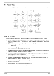
... Information" on page 120. 3. Reconnect the power and reboot the computer. 4. Remove any stored power by one until the failure point is selected. Reseat the memory modules. 7. Chapter 4 121 On this model). Disconnect power and all external devices including port replicators or docking stations. No Display Issue If the Display doesn... FRUs: No POST or Video If the POST or video doesn't display, perform the following actions one at a time to correct the problem. Drain any memory cards and CD/DVD discs.
... Information" on page 120. 3. Reconnect the power and reboot the computer. 4. Remove any stored power by one until the failure point is selected. Reseat the memory modules. 7. Chapter 4 121 On this model). Disconnect power and all external devices including port replicators or docking stations. No Display Issue If the Display doesn... FRUs: No POST or Video If the POST or video doesn't display, perform the following actions one at a time to correct the problem. Drain any memory cards and CD/DVD discs.

Service Guide
Page 133
... be replaced. If the computer is virus free. 3. If the Issue is still not resolved, see "Online Support Information" on page 42. 5. Run the Windows Memory Diagnostic from the BIOS, the drive may reduce display brightness.
... be replaced. If the computer is virus free. 3. If the Issue is still not resolved, see "Online Support Information" on page 42. 5. Run the Windows Memory Diagnostic from the BIOS, the drive may reduce display brightness.

Service Guide
Page 138
... the computer. b. Click Next. d. Select Repair your computer. e. g. Select Startup Repair. h. Startup Repair attempts to correct the problem. 1. When complete, click Finish. Run the Windows Memory Diagnostic Tool. For more information see Windows Help and Support. 10. Ensure all external devices. 2. Remove any key to start to ensure the computer is...
... the computer. b. Click Next. d. Select Repair your computer. e. g. Select Startup Repair. h. Startup Repair attempts to correct the problem. 1. When complete, click Finish. Run the Windows Memory Diagnostic Tool. For more information see Windows Help and Support. 10. Ensure all external devices. 2. Remove any key to start to ensure the computer is...

Service Guide
Page 146
... IN POST flag Initialize CPU registers Enable CPU cache Initialize caches to 4 GB Enable A20 line Autosize DRAM Initialize POST Memory Manager Clear 512 KB base RAM RAM failure on address line xxxx* RAM failure on data bits xxxx* of low byte of...describe the POST codes and descriptions during warm boot Initialize PCI Bus Mastering devices Initialize keyboard controller BIOS ROM checksum Initialize cache before memory autosize timer initialization DMA controller initialization Reset Programmable Interrupt Controller Test DRAM refresh Test 8742 Keyboard Controller Set ES segment register to ...
... IN POST flag Initialize CPU registers Enable CPU cache Initialize caches to 4 GB Enable A20 line Autosize DRAM Initialize POST Memory Manager Clear 512 KB base RAM RAM failure on address line xxxx* RAM failure on data bits xxxx* of low byte of...describe the POST codes and descriptions during warm boot Initialize PCI Bus Mastering devices Initialize keyboard controller BIOS ROM checksum Initialize cache before memory autosize timer initialization DMA controller initialization Reset Programmable Interrupt Controller Test DRAM refresh Test 8742 Keyboard Controller Set ES segment register to ...

Service Guide
Page 147
... interrupts Initialize POST display service Display prompt Press F2 to enter SETUP Disable CPU cache Test RAM between 512 and 640 KB Test extended memory Test extended memory address lines Jump to UserPatch1 Configure advanced cache registers Initialize Multi Processor APIC Enable external and CPU caches Setup System Management Mode (SMM) area...
... interrupts Initialize POST display service Display prompt Press F2 to enter SETUP Disable CPU cache Test RAM between 512 and 640 KB Test extended memory Test extended memory address lines Jump to UserPatch1 Configure advanced cache registers Initialize Multi Processor APIC Enable external and CPU caches Setup System Management Mode (SMM) area...


