
Aspire 5515 Quick Guide - EN
Page 3
... on how your notebook. Your guides To help you use Adobe Reader, access the Help and Support menu. It covers basic topics such as system utilities, data recovery, expansion options and troubleshooting. For more productive, please refer to functions or features which are marked in the model you get started with language such as the AcerSystem User Guide mentioned below will run the Adobe Reader setup program first. Please...
... on how your notebook. Your guides To help you use Adobe Reader, access the Help and Support menu. It covers basic topics such as system utilities, data recovery, expansion options and troubleshooting. For more productive, please refer to functions or features which are marked in the model you get started with language such as the AcerSystem User Guide mentioned below will run the Adobe Reader setup program first. Please...
Aspire 5515 Quick Guide - EN
Page 6
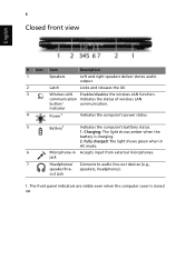
Fully charged: The light shows green when in AC mode. 6 Microphone-in Accepts input from external microphones. out jack 1. Charging: The light shows amber when the battery is closed up. The front panel indicators are visible even when the computer cover is charging. 2. communication Indicates the status of wireless LAN button/ communication. jack 7 Headphones/ Connects to audio line-out devices (e.g., speaker/line- speakers, headphones). indicator 4 Power1 Indicates the computer's power status. 5 Battery1 Indicates the computer's batttery status...
Fully charged: The light shows green when in AC mode. 6 Microphone-in Accepts input from external microphones. out jack 1. Charging: The light shows amber when the battery is closed up. The front panel indicators are visible even when the computer cover is charging. 2. communication Indicates the status of wireless LAN button/ communication. jack 7 Headphones/ Connects to audio line-out devices (e.g., speaker/line- speakers, headphones). indicator 4 Power1 Indicates the computer's power status. 5 Battery1 Indicates the computer's batttery status...
Aspire 5515 Quick Guide - EN
Page 10
... battery pack BIOS user, supervisor, HDD passwords Kensington lock slot ACPI 3.0 48.8 W 4400 mAh 3-pin 65 W AC adapter 88-/89-key keyboard Touchpad pointing device USB 2.0 port External display (VGA) port Headphones/speaker/line-out jack Microphone-in jack Ethernet (RJ-45) port DC-in microphone Integrated webcam* WLAN: IEEE 802.11b/g LAN: Fast Ethernet; 10 English Specifications Operating • system Platform • • • System memory • • Display • Graphics • Storage • subsystem • Audio •...
... battery pack BIOS user, supervisor, HDD passwords Kensington lock slot ACPI 3.0 48.8 W 4400 mAh 3-pin 65 W AC adapter 88-/89-key keyboard Touchpad pointing device USB 2.0 port External display (VGA) port Headphones/speaker/line-out jack Microphone-in jack Ethernet (RJ-45) port DC-in microphone Integrated webcam* WLAN: IEEE 802.11b/g LAN: Fast Ethernet; 10 English Specifications Operating • system Platform • • • System memory • • Display • Graphics • Storage • subsystem • Audio •...
Service Guide
Page 7
... 8 Indicators 9 TouchPad Basics (with fingerprint reader 10 Using the Keyboard 11 Lock Keys and embedded numeric keypad 11 Windows Keys 12 Hot Keys 13 Special Key 14 Using the System Utilities 15 Acer GridVista (dual-display compatible 15 Hardware Specifications and Configurations 16 System Utilities 21 BIOS Setup Utility 21 Navigating the BIOS Utility 21 Information 22 Main 23 Advanced 24 Security 26 Power 29 Boot 30 Exit 31 BIOS Flash Utilities 32 DOS Flash Utility 33 WinFlash Utility 35 Remove HDD/BIOS Password Utilities 36 Machine Disassembly and Replacement...
... 8 Indicators 9 TouchPad Basics (with fingerprint reader 10 Using the Keyboard 11 Lock Keys and embedded numeric keypad 11 Windows Keys 12 Hot Keys 13 Special Key 14 Using the System Utilities 15 Acer GridVista (dual-display compatible 15 Hardware Specifications and Configurations 16 System Utilities 21 BIOS Setup Utility 21 Navigating the BIOS Utility 21 Information 22 Main 23 Advanced 24 Security 26 Power 29 Boot 30 Exit 31 BIOS Flash Utilities 32 DOS Flash Utility 33 WinFlash Utility 35 Remove HDD/BIOS Password Utilities 36 Machine Disassembly and Replacement...

Service Guide
Page 8
... TouchPad 102 Replacing the TouchPad Bracket 103 Replacing the TouchPad Mylar Cover 103 Replacing the Upper Case 105 Replacing the LCD Module 106 Replacing the Keyboard 109 Replacing the Switch Cover 110 Replacing the Thermal Module 110 Replacing the CPU Fan Module 112 Replacing the Hard Disk Drive Module 112 Replacing the WLAN Module 114 Replacing the DIMM Modules 114 Replacing the ODD Module 115 Replacing the Lower Covers 116 Replacing the Battery 117 Troubleshooting 119 Common Problems 119 Power On Issue 120 No Display Issue 121 Random Loss of BIOS Settings...
... TouchPad 102 Replacing the TouchPad Bracket 103 Replacing the TouchPad Mylar Cover 103 Replacing the Upper Case 105 Replacing the LCD Module 106 Replacing the Keyboard 109 Replacing the Switch Cover 110 Replacing the Thermal Module 110 Replacing the CPU Fan Module 112 Replacing the Hard Disk Drive Module 112 Replacing the WLAN Module 114 Replacing the DIMM Modules 114 Replacing the ODD Module 115 Replacing the Lower Covers 116 Replacing the Battery 117 Troubleshooting 119 Common Problems 119 Power On Issue 120 No Display Issue 121 Random Loss of BIOS Settings...

Service Guide
Page 14
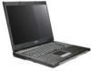
... button/indicator Speakers Keyboard Palmrest Enables/disables the wireless LAN function. Comfortable support area for selected models). Chapter 1 Integrated webcam Display screen Power button Web camera for video communication (for your hands when you around your new computer. Indicates the status of wireless LAN communication. Front View No. 1 2 3 4 5 6 7 8 4 Icon Item Microphone Description Internal microphone for sound recording. Left and right speakers deliver stereo audio output. Also called Liquid-Crystal Display (LCD), displays computer output. Your Acer Notebook...
... button/indicator Speakers Keyboard Palmrest Enables/disables the wireless LAN function. Comfortable support area for selected models). Chapter 1 Integrated webcam Display screen Power button Web camera for video communication (for your hands when you around your new computer. Indicates the status of wireless LAN communication. Front View No. 1 2 3 4 5 6 7 8 4 Icon Item Microphone Description Internal microphone for sound recording. Left and right speakers deliver stereo audio output. Also called Liquid-Crystal Display (LCD), displays computer output. Your Acer Notebook...
Service Guide
Page 33
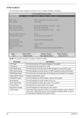
...: UUID: S2N250Y001832099561601 Aspire..5515 Aspire 39323232393932643635001EEC5A9BCF F1 Help Esc Exit ↑↓ Select Item ←→ Select Menu F5/F6 Change Values F9 Setup Defaults Enter SelectXSub-Menu F10 Save and Exit NOTE: The system information is an identifier standard used in the system. Parameter CPU Type CPU Speed IDE0 Model Name IDE0 Serial Number ATAPI Model Name System BIOS Version VGA BIOS Version Serial Number Asset Tag Number Product Name Manufacturer...
...: UUID: S2N250Y001832099561601 Aspire..5515 Aspire 39323232393932643635001EEC5A9BCF F1 Help Esc Exit ↑↓ Select Item ←→ Select Menu F5/F6 Change Values F9 Setup Defaults Enter SelectXSub-Menu F10 Save and Exit NOTE: The system information is an identifier standard used in the system. Parameter CPU Type CPU Speed IDE0 Model Name IDE0 Serial Number ATAPI Model Name System BIOS Version VGA BIOS Version Serial Number Asset Tag Number Product Name Manufacturer...
Service Guide
Page 35
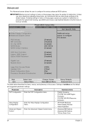
... screen allows the user to configure PCI devices USB Host Controller: Legacy USB Support: Option ROM Placement [Enabled] [Enabled] [Disabled] Gigabit Lan Network Boot: [Enabled] [Enabled] Large Disk Access Mode: Installed O/S: Reset Configuration Data: Processor Assisted Virtualization: [DOS] [Other] [No] [Enabled] F1 Help Esc Exit ↑↓ Select Item ←→ Select Menu F5/F6 Change Values F9 Setup Defaults Enter SelectXSub-Menu F10 Save and Exit The table below describes the items, menus, and submenus in this screen. Parameter PnP Configuration Video Display...
... screen allows the user to configure PCI devices USB Host Controller: Legacy USB Support: Option ROM Placement [Enabled] [Enabled] [Disabled] Gigabit Lan Network Boot: [Enabled] [Enabled] Large Disk Access Mode: Installed O/S: Reset Configuration Data: Processor Assisted Virtualization: [DOS] [Other] [No] [Enabled] F1 Help Esc Exit ↑↓ Select Item ←→ Select Menu F5/F6 Change Values F9 Setup Defaults Enter SelectXSub-Menu F10 Save and Exit The table below describes the items, menus, and submenus in this screen. Parameter PnP Configuration Video Display...
Service Guide
Page 37
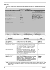
... Boot: [Disabled] F1 Help Esc Exit ↑↓ Select Item ←→ Select Menu F5/F6 Change Values F9 Setup Defaults Enter SelectXSub-Menu F10 Save and Exit The table below describes the parameters in this password protects the BIOS Setup Utility from unauthorized access. Shows the setting of the user password. Enter HDD 0 Password. Don't forget your computer from unauthorized use. Press Enter to set , this group happened. Option Clear or Set Clear or Set Clear or Set N/A N/A N/A Disabled...
... Boot: [Disabled] F1 Help Esc Exit ↑↓ Select Item ←→ Select Menu F5/F6 Change Values F9 Setup Defaults Enter SelectXSub-Menu F10 Save and Exit The table below describes the parameters in this password protects the BIOS Setup Utility from unauthorized access. Shows the setting of the user password. Enter HDD 0 Password. Don't forget your computer from unauthorized use. Press Enter to set , this group happened. Option Clear or Set Clear or Set Clear or Set N/A N/A N/A Disabled...
Service Guide
Page 38
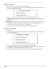
... on boot parameter. 5. Removing a Password Follow these steps as you can not exceeds 8 alphanumeric characters (A-Z, a-z, 0-9, not case sensitive). The Set Password box appears: 2. When you are done, press F10 to save the changes and exit the BIOS Setup Utility. Press Enter. After setting the password, the computer sets the User Password parameter to "Clear". 4. The computer then sets the Supervisor Password parameter to "Set". 4. Use the ↑ and ↓ keys to...
... on boot parameter. 5. Removing a Password Follow these steps as you can not exceeds 8 alphanumeric characters (A-Z, a-z, 0-9, not case sensitive). The Set Password box appears: 2. When you are done, press F10 to save the changes and exit the BIOS Setup Utility. Press Enter. After setting the password, the computer sets the User Password parameter to "Clear". 4. The computer then sets the Supervisor Password parameter to "Set". 4. Use the ↑ and ↓ keys to...

Service Guide
Page 39
... BIOS Setup Utility. When you the Setup Warning. If the new password and confirm new password strings do not match, the screen will display as following message. 28 Chapter 2 If desired, you can enable the Password on boot parameter. 6. The password setting is OK, the screen will display the following . Use the ↑ and ↓ keys to "Set". 5. The Set Password box appears. 2. Press Enter. If the verification is complete after the user presses Enter. Type...
... BIOS Setup Utility. When you the Setup Warning. If the new password and confirm new password strings do not match, the screen will display as following message. 28 Chapter 2 If desired, you can enable the Password on boot parameter. 6. The password setting is OK, the screen will display the following . Use the ↑ and ↓ keys to "Set". 5. The Set Password box appears. 2. Press Enter. If the verification is complete after the user presses Enter. Type...
Service Guide
Page 130
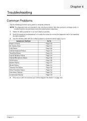
... symptoms by attempting to test only Acer products. Non-Acer products, prototype cards, or modified options can give false errors and invalid system responses. 1. Symptoms (Verified) Go To Power On Issue Page 120 No Display Issue Page 121 LCD Failure Page 123 Internal Keyboard Failure Page 123 TouchPad Failure Page 124 Internal Speaker Failure Page 124 Internal Microphone Failure Page 126 ODD Failure Page...
... symptoms by attempting to test only Acer products. Non-Acer products, prototype cards, or modified options can give false errors and invalid system responses. 1. Symptoms (Verified) Go To Power On Issue Page 120 No Display Issue Page 121 LCD Failure Page 123 Internal Keyboard Failure Page 123 TouchPad Failure Page 124 Internal Speaker Failure Page 124 Internal Microphone Failure Page 126 ODD Failure Page...
Service Guide
Page 132
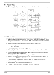
... power, see "Online Support Information" on page 163. Do not replace a non-defective FRUs: No POST or Video If the POST or video doesn't display, perform the following actions one at a time to correct the problem. Make sure the computer has power by removing the power cable and battery and holding down the power button for specific model procedures. 2. If the POST or video appears on the external display, see "Disassembly...
... power, see "Online Support Information" on page 163. Do not replace a non-defective FRUs: No POST or Video If the POST or video doesn't display, perform the following actions one at a time to correct the problem. Make sure the computer has power by removing the power cable and battery and holding down the power button for specific model procedures. 2. If the POST or video appears on the external display, see "Disassembly...

Service Guide
Page 133
... "Online Support Information" on page 163. If display size is only abnormal in an application, check the view settings and control/mouse wheel zoom feature in the same location, the LCD is missing from the operating system DVD and follow the onscreen prompts. 11. Roll back the video driver to correct the problem. 1. Run the Windows Memory Diagnostic from the BIOS, the drive may reduce display brightness. Random...
... "Online Support Information" on page 163. If display size is only abnormal in an application, check the view settings and control/mouse wheel zoom feature in the same location, the LCD is missing from the operating system DVD and follow the onscreen prompts. 11. Roll back the video driver to correct the problem. 1. Run the Windows Memory Diagnostic from the BIOS, the drive may reduce display brightness. Random...

Service Guide
Page 138
... Restore. The System Recovery Options screen displays. Chapter 4 127 g. Select Startup Repair. If an issue is discovered, follow the onscreen information to ensure the computer is not fixed, repeat the preceding steps and select an earlier time and date. 11. f. Click Next. Select the appropriate operating system, and click Next. h. Remove any key to start to enter the BIOS Utility. Run the Windows Vista Startup Repair Utility: a. e. b. Select Repair your computer. Replace...
... Restore. The System Recovery Options screen displays. Chapter 4 127 g. Select Startup Repair. If an issue is discovered, follow the onscreen information to ensure the computer is not fixed, repeat the preceding steps and select an earlier time and date. 11. f. Click Next. Select the appropriate operating system, and click Next. h. Remove any key to start to enter the BIOS Utility. Run the Windows Vista Startup Repair Utility: a. e. b. Select Repair your computer. Replace...

Service Guide
Page 141
... the drive, motherboard, and cables. Try an alternate cable, if available. Replace the ODD. If the drive works with alternate discs, the original disc is identical to one at a time to correct the problem. 1. Restart the computer and press F2 to the ODD. Turn off the power and remove the cover to inspect the connections to enter the BIOS Utility. 2. If the drive works with the new cable, the original cable should be replaced. 4. Remove...
... the drive, motherboard, and cables. Try an alternate cable, if available. Replace the ODD. If the drive works with alternate discs, the original disc is identical to one at a time to correct the problem. 1. Restart the computer and press F2 to the ODD. Turn off the power and remove the cover to inspect the connections to enter the BIOS Utility. 2. If the drive works with the new cable, the original cable should be replaced. 4. Remove...

Service Guide
Page 143
... yellow exclamation marks. • There are no device conflicts. 132 Chapter 4 Restore system and file settings from a known good date using System Restore. If the mouse uses a USB connection, try an alternate USB port. 4. If the issue is properly installed. See the mouse user manual. 3. Roll back the mouse driver to verify mouse operation. If the mouse uses a wireless connection, insert new batteries and confirm there is a good connection. Run the Event Viewer to check the...
... yellow exclamation marks. • There are no device conflicts. 132 Chapter 4 Restore system and file settings from a known good date using System Restore. If the mouse uses a USB connection, try an alternate USB port. 4. If the issue is properly installed. See the mouse user manual. 3. Roll back the mouse driver to verify mouse operation. If the mouse uses a wireless connection, insert new batteries and confirm there is a good connection. Run the Event Viewer to check the...

Service Guide
Page 147
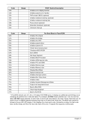
... vectors POST device initialization Check ROM copyright notice Check video configuration against CMOS Initialize PCI bus and devices Initialize all video adapters in system QuietBoot start (optional) Shadow video BIOS ROM Display BIOS copyright notice Display CPU type and speed Initialize EISA board Test keyboard Set key click if enabled Test for unexpected interrupts Initialize POST display service Display prompt Press F2 to enter SETUP Disable CPU cache Test RAM between 512 and 640 KB Test extended memory Test extended memory address lines...
... vectors POST device initialization Check ROM copyright notice Check video configuration against CMOS Initialize PCI bus and devices Initialize all video adapters in system QuietBoot start (optional) Shadow video BIOS ROM Display BIOS copyright notice Display CPU type and speed Initialize EISA board Test keyboard Set key click if enabled Test for unexpected interrupts Initialize POST display service Display prompt Press F2 to enter SETUP Disable CPU cache Test RAM between 512 and 640 KB Test extended memory Test extended memory address lines...

Service Guide
Page 148
... Routine Description Configure Motherboard Configurable Devices (optional) Initialize BIOS Data Area Enable Non-Maskable Interrupts (NMIs) Initialize Extended BIOS Data Area Test and initialize PS/2 mouse Initialize floppy controller Determine number of day Check key lock Initialize Typematic rate Erase F2 prompt Scan for F2 key stroke Enter SETUP Clear Boot flag Check for errors POST done - prepare to boot operating system One short beep before boot Terminate QuietBoot (optional) Check password (optional) Prepare Boot Initialize...
... Routine Description Configure Motherboard Configurable Devices (optional) Initialize BIOS Data Area Enable Non-Maskable Interrupts (NMIs) Initialize Extended BIOS Data Area Test and initialize PS/2 mouse Initialize floppy controller Determine number of day Check key lock Initialize Typematic rate Erase F2 prompt Scan for F2 key stroke Enter SETUP Clear Boot flag Check for errors POST done - prepare to boot operating system One short beep before boot Terminate QuietBoot (optional) Check password (optional) Prepare Boot Initialize...
Service Guide
Page 149
... CPU Initialize system timer Initialize system I/O Check force recovery boot Checksum BIOS ROM Go to BIOS Set Huge Segment Initialize Multi Processor Initialize OEM special code Initialize PIC and DMA Initialize Memory type Initialize Memory size Shadow Boot Block System memory test Initialize interrupt vectors Initialize Run Time Clock Initialize video Initialize System Management Mode Output one beep before boot Boot to Mini DOS Clear Huge Segment Boot to the port...
... CPU Initialize system timer Initialize system I/O Check force recovery boot Checksum BIOS ROM Go to BIOS Set Huge Segment Initialize Multi Processor Initialize OEM special code Initialize PIC and DMA Initialize Memory type Initialize Memory size Shadow Boot Block System memory test Initialize interrupt vectors Initialize Run Time Clock Initialize video Initialize System Management Mode Output one beep before boot Boot to Mini DOS Clear Huge Segment Boot to the port...


