
Intel Smart Response Installation Guide
Page 1
... performance testing, chose "Maximized" mode. 7. For the new version RST driver, please check our website for the latest information: http://www.asrock.com * Before you intend to show the newly accelerated system configuration. * Intel® will update the new version RST driver in Icon ... Mode]. For all required drivers, including RST storage driver version 10.5 or later. 2. Intel Smart Response Technology Installation Guide This motherboard supports Intel Smart Response Technology. You can find the UI setup instruction and the step by double-clicking RST Storage icon in the...
... performance testing, chose "Maximized" mode. 7. For the new version RST driver, please check our website for the latest information: http://www.asrock.com * Before you intend to show the newly accelerated system configuration. * Intel® will update the new version RST driver in Icon ... Mode]. For all required drivers, including RST storage driver version 10.5 or later. 2. Intel Smart Response Technology Installation Guide This motherboard supports Intel Smart Response Technology. You can find the UI setup instruction and the step by double-clicking RST Storage icon in the...

Intel Rapid Storage Guide
Page 12
...) In order to install an operating system onto a RAID volume, the RAID option must be enabled in System BIOS Use the instructions included with your motherboard to select the drive.
...) In order to install an operating system onto a RAID volume, the RAID option must be enabled in System BIOS Use the instructions included with your motherboard to select the drive.
RAID Installation Guide
Page 2
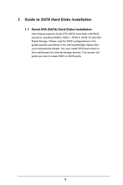
Please read the RAID configurations in this motherboard for internal storage devices. This section will guide you how to create RAID on this guide carefully according to SATA Hard Disks Installation 1.1 Serial ATA (SATA) Hard Disks Installation Intel chipset supports Serial ATA (SATA) hard disks with RAID functions, including RAID 0, RAID 1, RAID 5, RAID 10 and Intel Rapid Storage. You may install SATA hard disks on SATA ports. 2 1. Guide to the Intel southbridge chipset that your motherboard adopts.
Please read the RAID configurations in this motherboard for internal storage devices. This section will guide you how to create RAID on this guide carefully according to SATA Hard Disks Installation 1.1 Serial ATA (SATA) Hard Disks Installation Intel chipset supports Serial ATA (SATA) hard disks with RAID functions, including RAID 0, RAID 1, RAID 5, RAID 10 and Intel Rapid Storage. You may install SATA hard disks on SATA ports. 2 1. Guide to the Intel southbridge chipset that your motherboard adopts.
RAID Installation Guide
Page 3
For optimal performance, please install identical drives of RAID This motherboard adopts Intel southbridge chipset that integrates RAID controller supporting RAID 0 / RAID 1/ Intel Rapid Storage / RAID 10 / RAID 5 function with four independent Serial ATA (SATA) channels. ...
For optimal performance, please install identical drives of RAID This motherboard adopts Intel southbridge chipset that integrates RAID controller supporting RAID 0 / RAID 1/ Intel Rapid Storage / RAID 10 / RAID 5 function with four independent Serial ATA (SATA) channels. ...
RAID Installation Guide
Page 18
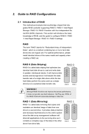
STEP 1: Copy Intel® RAID drivers into a USB flash disk You can download the drivers from ASRock's website and unzip the files into a USB flash disk or copy the files from ASRock's motherboard support CD. (Please copy the files under the following directory: 32 bit: ..\i386\Win7_Intel.. 64-bit: ..\AMD64\Win7-64_Intel.. STEP 2: Install...
STEP 1: Copy Intel® RAID drivers into a USB flash disk You can download the drivers from ASRock's website and unzip the files into a USB flash disk or copy the files from ASRock's motherboard support CD. (Please copy the files under the following directory: 32 bit: ..\i386\Win7_Intel.. 64-bit: ..\AMD64\Win7-64_Intel.. STEP 2: Install...
RAID Installation Guide
Page 20
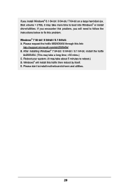
... need to follow the instructions below to boot into Windows® or install driver/utilities. E. Disk volume > 2TB), it may take about 5 minutes to install motherboard drivers and utilities. 20 Windows® 7 64-bit / 8 64-bit / 8.1 64-bit: A. If you will install this hotfix then reboot by itself. If you encounter...
... need to follow the instructions below to boot into Windows® or install driver/utilities. E. Disk volume > 2TB), it may take about 5 minutes to install motherboard drivers and utilities. 20 Windows® 7 64-bit / 8 64-bit / 8.1 64-bit: A. If you will install this hotfix then reboot by itself. If you encounter...

User Manual
Page 2
... change without written consent of this documentation. Version 1.0 Published April 2014 Copyright©2014 ASRock INC. CALIFORNIA, USA ONLY The Lithium battery adopted on this motherboard contains Perchlorate, a toxic substance controlled in Perchlorate Best Management Practices (BMP) regulations passed ..., except duplication of the FCC Rules. Disclaimer: Specifications and information contained in advance. Copyright Notice: No part of ASRock Inc. In no responsibility for a particular purpose. This device complies with Part 15 of documentation by the California Legislature...
... change without written consent of this documentation. Version 1.0 Published April 2014 Copyright©2014 ASRock INC. CALIFORNIA, USA ONLY The Lithium battery adopted on this motherboard contains Perchlorate, a toxic substance controlled in Perchlorate Best Management Practices (BMP) regulations passed ..., except duplication of the FCC Rules. Disclaimer: Specifications and information contained in advance. Copyright Notice: No part of ASRock Inc. In no responsibility for a particular purpose. This device complies with Part 15 of documentation by the California Legislature...

User Manual
Page 4
Contents Chapter 1 Introduction 1 1.1 Package Contents 1 1.2 Specifications 2 1.3 Unique Features 6 1.4 Motherboard Layout 10 1.5 I/O Panel 12 Chapter 2 Installation 14 2.1 Installing the CPU 15 2.2 Installing the CPU Fan and Heatsink 18 2.3 Installing Memory Modules (DIMM) 19 2.4 Expansion Slots (... Setup 30 Chapter 3 Software and Utilities Operation 31 3.1 Installing Drivers 31 3.2 A-Tuning 32 3.3 Intel® Rapid Start Technology 38 3.4 Intel® Smart Connect Technology 43 3.5 ASRock Cloud 48
Contents Chapter 1 Introduction 1 1.1 Package Contents 1 1.2 Specifications 2 1.3 Unique Features 6 1.4 Motherboard Layout 10 1.5 I/O Panel 12 Chapter 2 Installation 14 2.1 Installing the CPU 15 2.2 Installing the CPU Fan and Heatsink 18 2.3 Installing Memory Modules (DIMM) 19 2.4 Expansion Slots (... Setup 30 Chapter 3 Software and Utilities Operation 31 3.1 Installing Drivers 31 3.2 A-Tuning 32 3.3 Intel® Rapid Start Technology 38 3.4 Intel® Smart Connect Technology 43 3.5 ASRock Cloud 48
User Manual
Page 7
... notice. If you require technical support related to quality and endurance. ASRock website http://www.asrock.com. 1.1 Package Contents • ASRock Z97M Pro4 Motherboard (Micro ATX Form Factor) • ASRock Z97M Pro4 Quick Installation Guide • ASRock Z97M Pro4 Support CD • 2 x Serial ATA (SATA) Data Cables (Optional) • 1 x I/O Panel Shield 1 English Z97M Pro4 Chapter 1 Introduction Thank you are using. In this manual will...
... notice. If you require technical support related to quality and endurance. ASRock website http://www.asrock.com. 1.1 Package Contents • ASRock Z97M Pro4 Motherboard (Micro ATX Form Factor) • ASRock Z97M Pro4 Quick Installation Guide • ASRock Z97M Pro4 Support CD • 2 x Serial ATA (SATA) Data Cables (Optional) • 1 x I/O Panel Shield 1 English Z97M Pro4 Chapter 1 Introduction Thank you are using. In this manual will...

User Manual
Page 12
...names, capacities, temperatures, SMART info, health status, and other information of your motherboard up to windows automatically! 6 English You can easily optimize your system and keep your HDDs here. ASRock USB Key In a world where time is subject to get connected with your ... more new features and improved utilities. Why should we even bother memorizing those foot long passwords? 1.3 Unique Features ASRock Super Alloy This motherboard is ASRock's multi purpose software suite with a new interface, more durable performance, including Premium Alloy Choke, NexFETTM MOSFET, and Sapphire...
...names, capacities, temperatures, SMART info, health status, and other information of your motherboard up to windows automatically! 6 English You can easily optimize your system and keep your HDDs here. ASRock USB Key In a world where time is subject to get connected with your ... more new features and improved utilities. Why should we even bother memorizing those foot long passwords? 1.3 Unique Features ASRock Super Alloy This motherboard is ASRock's multi purpose software suite with a new interface, more durable performance, including Premium Alloy Choke, NexFETTM MOSFET, and Sapphire...
User Manual
Page 15
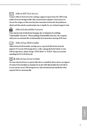
... then you to copy the RAID driver from the support CD to your USB storage device. Z97M Pro4 ASRock UEFI Tech Service Contact ASRock Tech Service by enabling "Dehumidifier Function". ASRock Dehumidifier Function Users may try to dampness by sending a support request from the UEFI setup utility ...if you are having trouble with your system via an USB storage device, then downloads and installs the other required drivers automatically. 9 English Users may prevent motherboard...
... then you to copy the RAID driver from the support CD to your USB storage device. Z97M Pro4 ASRock UEFI Tech Service Contact ASRock Tech Service by enabling "Dehumidifier Function". ASRock Dehumidifier Function Users may try to dampness by sending a support request from the UEFI setup utility ...if you are having trouble with your system via an USB storage device, then downloads and installs the other required drivers automatically. 9 English Users may prevent motherboard...

User Manual
Page 16
1.4 Motherboard Layout USB 2.0 T: USB0 B: USB1 Ps2 Keyboard/ Mouse HDMI1 PWR_FAN1 CPU_FAN2 CPU_FAN1 ATX12V1 DVI1 VGA1 DDR3_A1 (64 bit, 240-pin module) DDR3_A2 (64 bit, 240-pin ... B: USB5 Top: RJ-45 Top: Central/Bass LINE IN Center: REAR SPK FRONT Top: Center: 1 HD_AUDIO1 Audio CODEC CHA_FAN2 CLRCMOS1 1 CMOS Battery PCI Express 3.0 PCIE1 Z97M Pro4 PCI1 Super I/O COM1 1 1 PCI2 LPT1 RoHS PCIE2 1 CI1 TPMS1 USB6_7 1 1 USB8_9 1 Intel Z97 TB1 CHA_FAN1 PLED PWRBTN 1 HDLED RESET PANEL1 64Mb BIOS SPEAKER1 1 Bottom: Optical...
1.4 Motherboard Layout USB 2.0 T: USB0 B: USB1 Ps2 Keyboard/ Mouse HDMI1 PWR_FAN1 CPU_FAN2 CPU_FAN1 ATX12V1 DVI1 VGA1 DDR3_A1 (64 bit, 240-pin module) DDR3_A2 (64 bit, 240-pin ... B: USB5 Top: RJ-45 Top: Central/Bass LINE IN Center: REAR SPK FRONT Top: Center: 1 HD_AUDIO1 Audio CODEC CHA_FAN2 CLRCMOS1 1 CMOS Battery PCI Express 3.0 PCIE1 Z97M Pro4 PCI1 Super I/O COM1 1 1 PCI2 LPT1 RoHS PCIE2 1 CI1 TPMS1 USB6_7 1 1 USB8_9 1 Intel Z97 TB1 CHA_FAN1 PLED PWRBTN 1 HDLED RESET PANEL1 64Mb BIOS SPEAKER1 1 Bottom: Optical...

User Manual
Page 20
...to use a grounded wrist strap or touch a safety grounded object before installing or removing the motherboard components. Chapter 2 Installation This is a Micro ATX form factor motherboard. Failure to the motherboard's components, NEVER place your chassis to unplug the power cord before you handle the components....with the components. • When placing screws to secure the motherboard to the chassis, please do so may damage the motherboard. 14 English Doing so may cause physical injuries and damages to motherboard components. • In order to avoid damage from static electricity...
...to use a grounded wrist strap or touch a safety grounded object before installing or removing the motherboard components. Chapter 2 Installation This is a Micro ATX form factor motherboard. Failure to the motherboard's components, NEVER place your chassis to unplug the power cord before you handle the components....with the components. • When placing screws to secure the motherboard to the chassis, please do so may damage the motherboard. 14 English Doing so may cause physical injuries and damages to motherboard components. • In order to avoid damage from static electricity...

User Manual
Page 23
The cover must be placed if you wish to return the motherboard for after service. 17 English Z97M Pro4 Please save and replace the cover if the processor is removed.
The cover must be placed if you wish to return the motherboard for after service. 17 English Z97M Pro4 Please save and replace the cover if the processor is removed.

User Manual
Page 25
...the slot at incorrect orientation. For dual channel configuration, you force the DIMM into a DDR3 slot; It is not allowed to the motherboard and the DIMM if you always need to activate Dual Channel Memory Technology with only one correct orientation. Dual Channel Memory Configuration Priority .... 3. It is unable to install identical (the same brand, speed, size and chip-type) DDR3 DIMM pairs. 2. Z97M Pro4 2.3 Installing Memory Modules (DIMM) This motherboard provides four 240-pin DDR3 (Double Data Rate 3) DIMM slots, and supports Dual Channel Memory Technology. 1.
...the slot at incorrect orientation. For dual channel configuration, you force the DIMM into a DDR3 slot; It is not allowed to the motherboard and the DIMM if you always need to activate Dual Channel Memory Technology with only one correct orientation. Dual Channel Memory Configuration Priority .... 3. It is unable to install identical (the same brand, speed, size and chip-type) DDR3 DIMM pairs. 2. Z97M Pro4 2.3 Installing Memory Modules (DIMM) This motherboard provides four 240-pin DDR3 (Double Data Rate 3) DIMM slots, and supports Dual Channel Memory Technology. 1.

User Manual
Page 27
... sure that have 32-bit PCI interface. PCIe slots: PCIE1 (PCIe 3.0 x16 slot) is used for the card before you start the installation. English 21 Z97M Pro4 2.4 Expansion Slots (PCI and PCI Express Slots) There are used to the motherboard's chassis fan connector (CHA_FAN1 or CHA_FAN2) when using multiple graphics cards.
... sure that have 32-bit PCI interface. PCIe slots: PCIE1 (PCIe 3.0 x16 slot) is used for the card before you start the installation. English 21 Z97M Pro4 2.4 Expansion Slots (PCI and PCI Express Slots) There are used to the motherboard's chassis fan connector (CHA_FAN1 or CHA_FAN2) when using multiple graphics cards.

User Manual
Page 29
...keeps blinking when the system is in S1/S3 sleep state. When connecting your system using the power switch. You may differ by chassis. Z97M Pro4 2.6 Onboard Headers and Connectors Onboard headers and connectors are matched correctly. The LED is on the chassis front panel. Do NOT place jumper ...over the headers and connectors will cause permanent damage to turn off (S5). The front panel design may configure the way to the motherboard. Press the reset switch to restart the computer if the computer freezes and fails to the power switch on when the system is reading...
...keeps blinking when the system is in S1/S3 sleep state. When connecting your system using the power switch. You may differ by chassis. Z97M Pro4 2.6 Onboard Headers and Connectors Onboard headers and connectors are matched correctly. The LED is on the chassis front panel. Do NOT place jumper ...over the headers and connectors will cause permanent damage to turn off (S5). The front panel design may configure the way to the motherboard. Press the reset switch to restart the computer if the computer freezes and fails to the power switch on when the system is reading...

User Manual
Page 30
...+ GND IntA_PA_SSTXIntA_PA_SSTX+ GND IntA_PA_DIntA_PA_D+ Vbus IntA_PB_SSRXIntA_PB_SSRX+ GND IntA_PB_SSTXIntA_PB_SSTX+ GND IntA_PB_DIntA_PB_D+ Dummy 1 Besides four USB 3.0 ports on the I /O panel, there are two headers on this motherboard. Each USB 2.0 header can support two ports. Each USB 3.0 header can support two ports. English 24 USB 3.0 Header (19-pin USB10_11) (see p.10, No. ...SATA_4: see p.10, No. 9) (SATA_5: see p.10, No. 26) GND PRESENCE# MIC_RET OUT_RET 1 OUT2_L J_SENSE OUT2_R MIC2_R MIC2_L This header is one header on this motherboard.
...+ GND IntA_PA_SSTXIntA_PA_SSTX+ GND IntA_PA_DIntA_PA_D+ Vbus IntA_PB_SSRXIntA_PB_SSRX+ GND IntA_PB_SSTXIntA_PB_SSTX+ GND IntA_PB_DIntA_PB_D+ Dummy 1 Besides four USB 3.0 ports on the I /O panel, there are two headers on this motherboard. Each USB 2.0 header can support two ports. Each USB 3.0 header can support two ports. English 24 USB 3.0 Header (19-pin USB10_11) (see p.10, No. ...SATA_4: see p.10, No. 9) (SATA_5: see p.10, No. 26) GND PRESENCE# MIC_RET OUT_RET 1 OUT2_L J_SENSE OUT2_R MIC2_R MIC2_L This header is one header on this motherboard.

User Manual
Page 32
... 1-3. CPU Fan Connectors (4-pin CPU_FAN1) (see p.10, No. 4) (3-pin CPU_FAN2) (see p.10, No. 24) 12 24 1 13 8 5 4 1 This motherboard provides a 24-pin ATX power connector. This motherboard provides an 8-pin ATX 12V power connector. English 26 ATX Power Connector (24-pin ATXPWR1) (see p.10, No. 7) ATX 12V Power Connector... TB1) (see p.10, No. 18) Serial Port Header (9-pin COM1) (see p.10, No. 3) FAN_SPEED_CONTROL FAN_SPEED +12V GND 1 234 FAN_SPEED FAN_VOLTAGE GND This motherboard provides a 4-Pin CPU fan (Quiet Fan) connector. This COM1 header supports a serial port module.
... 1-3. CPU Fan Connectors (4-pin CPU_FAN1) (see p.10, No. 4) (3-pin CPU_FAN2) (see p.10, No. 24) 12 24 1 13 8 5 4 1 This motherboard provides a 24-pin ATX power connector. This motherboard provides an 8-pin ATX 12V power connector. English 26 ATX Power Connector (24-pin ATXPWR1) (see p.10, No. 7) ATX 12V Power Connector... TB1) (see p.10, No. 18) Serial Port Header (9-pin COM1) (see p.10, No. 3) FAN_SPEED_CONTROL FAN_SPEED +12V GND 1 234 FAN_SPEED FAN_VOLTAGE GND This motherboard provides a 4-Pin CPU fan (Quiet Fan) connector. This COM1 header supports a serial port module.

User Manual
Page 33
... SPD0 STB# This is an interface for print port cable that detects if the chassis cove has been removed. Z97M Pro4 Chassis Intrusion Header (2-pin CI1) (see p.10, No. 22) 1 GND Signal This motherboard supports CASE OPEN detection feature that allows convenient connection of printer devices. This feature requires a chassis with chassis intrusion...
... SPD0 STB# This is an interface for print port cable that detects if the chassis cove has been removed. Z97M Pro4 Chassis Intrusion Header (2-pin CI1) (see p.10, No. 22) 1 GND Signal This motherboard supports CASE OPEN detection feature that allows convenient connection of printer devices. This feature requires a chassis with chassis intrusion...

