
Intel Smart Response Installation Guide
Page 1
... accelerate AND the SSD in the near future. For the new version RST driver, please check our website for the latest information: http://www.asrock.com * Before you use RST function, you want to a RAID mode system, then install all performance testing, chose "Maximized" mode. 7....the screen. 4. For all required drivers, including RST storage driver version 10.5 or later. 2. Intel Smart Response Technology Installation Guide This motherboard supports Intel Smart Response Technology. You can find the UI setup instruction and the step by double-clicking RST Storage icon in RAID ROM....
... accelerate AND the SSD in the near future. For the new version RST driver, please check our website for the latest information: http://www.asrock.com * Before you use RST function, you want to a RAID mode system, then install all performance testing, chose "Maximized" mode. 7....the screen. 4. For all required drivers, including RST storage driver version 10.5 or later. 2. Intel Smart Response Technology Installation Guide This motherboard supports Intel Smart Response Technology. You can find the UI setup instruction and the step by double-clicking RST Storage icon in RAID ROM....

Intel Rapid Storage Guide
Page 12
... BIOS Setup program. Click F2 or Delete to enable RAID in the system BIOS. 1. Enable RAID in System BIOS Use the instructions included with your motherboard to enter the BIOS Setup program after the Power-On-Self-Test (POST) memory test begins. 2. Use the up or down arrow keys to select...
... BIOS Setup program. Click F2 or Delete to enable RAID in the system BIOS. 1. Enable RAID in System BIOS Use the instructions included with your motherboard to enter the BIOS Setup program after the Power-On-Self-Test (POST) memory test begins. 2. Use the up or down arrow keys to select...
RAID Installation Guide
Page 2
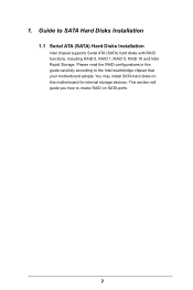
1. Guide to the Intel southbridge chipset that your motherboard adopts. Please read the RAID configurations in this motherboard for internal storage devices. This section will guide you how to create RAID on this guide carefully according to SATA Hard Disks Installation 1.1 Serial ATA (SATA) Hard Disks Installation Intel chipset supports Serial ATA (SATA) hard disks with RAID functions, including RAID 0, RAID 1, RAID 5, RAID 10 and Intel Rapid Storage. You may install SATA hard disks on SATA ports. 2
1. Guide to the Intel southbridge chipset that your motherboard adopts. Please read the RAID configurations in this motherboard for internal storage devices. This section will guide you how to create RAID on this guide carefully according to SATA Hard Disks Installation 1.1 Serial ATA (SATA) Hard Disks Installation Intel chipset supports Serial ATA (SATA) hard disks with RAID functions, including RAID 0, RAID 1, RAID 5, RAID 10 and Intel Rapid Storage. You may install SATA hard disks on SATA ports. 2
RAID Installation Guide
Page 3
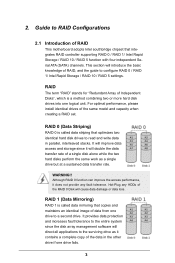
... write data in the other drive if one drive fails. 3 Although RAID 0 function can improve the access performance, it contains a complete copy of RAID This motherboard adopts Intel southbridge chipset that optimizes two identical hard disk drives to a second drive. 2. This section will cause data damage or data loss. RAID 0 (Data...
... write data in the other drive if one drive fails. 3 Although RAID 0 function can improve the access performance, it contains a complete copy of RAID This motherboard adopts Intel southbridge chipset that optimizes two identical hard disk drives to a second drive. 2. This section will cause data damage or data loss. RAID 0 (Data...
RAID Installation Guide
Page 18
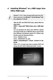
... boot. 18 STEP 1: Copy Intel® RAID drivers into a USB flash disk You can download the drivers from ASRock's website and unzip the files into a USB flash disk or copy the files from ASRock's motherboard support CD. (Please copy the files under the following directory: 32 bit: ..\i386\Win7_Intel.. 64-bit: ..\AMD64\Win7...
... boot. 18 STEP 1: Copy Intel® RAID drivers into a USB flash disk You can download the drivers from ASRock's website and unzip the files into a USB flash disk or copy the files from ASRock's motherboard support CD. (Please copy the files under the following directory: 32 bit: ..\i386\Win7_Intel.. 64-bit: ..\AMD64\Win7...
RAID Installation Guide
Page 20
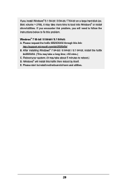
...; will need to follow the instructions below to fix this problem. Reboot your system. (It may take a long time; >30 mins.) C. E. Please start to install motherboard drivers and utilities. 20 Windows® 7 64-bit / 8 64-bit / 8.1 64-bit: A. After installing Windows® 7 64-bit / 8 64-bit / 8.1 64-bit, install the hotfix...
...; will need to follow the instructions below to fix this problem. Reboot your system. (It may take a long time; >30 mins.) C. E. Please start to install motherboard drivers and utilities. 20 Windows® 7 64-bit / 8 64-bit / 8.1 64-bit: A. After installing Windows® 7 64-bit / 8 64-bit / 8.1 64-bit, install the hotfix...

User Manual
Page 2
... in California, USA, please follow the related regulations in this documentation, ASRock does not provide warranty of the FCC Rules. Disclaimer: Specifications and information contained in this motherboard contains Perchlorate, a toxic substance controlled in this documentation may not be registered...including but not limited to infringe. Products and corporate names appearing in Perchlorate Best Management Practices (BMP) regulations passed by ASRock. "Perchlorate Material-special handling may appear in advance. Copyright Notice: No part of this documentation may or may be ...
... in California, USA, please follow the related regulations in this documentation, ASRock does not provide warranty of the FCC Rules. Disclaimer: Specifications and information contained in this motherboard contains Perchlorate, a toxic substance controlled in this documentation may not be registered...including but not limited to infringe. Products and corporate names appearing in Perchlorate Best Management Practices (BMP) regulations passed by ASRock. "Perchlorate Material-special handling may appear in advance. Copyright Notice: No part of this documentation may or may be ...

User Manual
Page 4
Contents Chapter 1 Introduction 1 1.1 Package Contents 1 1.2 Specifications 2 1.3 Motherboard Layout 6 1.4 I/O Panel 8 1.5 WiFi-802.11ac Module and ASRock WiFi 2.4/5 GHz Antenna 10 Chapter 2 Installation 15 2.1 Installing the CPU 16 2.2 Installing the CPU Fan and Heatsink 19 2.3 Installing Memory Modules (DIMM) 20 2.4... 3 Software and Utilities Operation 28 3.1 Installing Drivers 28 3.2 A-Tuning 29 3.3 Intel® Rapid Start Technology 35 3.4 Intel® Smart Connect Technology 40 3.5 ASRock Cloud 45 3.6 ASRock APP Shop 55 3.6.1 UI Overview 55 3.6.2 Apps 56
Contents Chapter 1 Introduction 1 1.1 Package Contents 1 1.2 Specifications 2 1.3 Motherboard Layout 6 1.4 I/O Panel 8 1.5 WiFi-802.11ac Module and ASRock WiFi 2.4/5 GHz Antenna 10 Chapter 2 Installation 15 2.1 Installing the CPU 16 2.2 Installing the CPU Fan and Heatsink 19 2.3 Installing Memory Modules (DIMM) 20 2.4... 3 Software and Utilities Operation 28 3.1 Installing Drivers 28 3.2 A-Tuning 29 3.3 Intel® Rapid Start Technology 35 3.4 Intel® Smart Connect Technology 40 3.5 ASRock Cloud 45 3.6 ASRock APP Shop 55 3.6.1 UI Overview 55 3.6.2 Apps 56

User Manual
Page 6
...-step installation guides. If you require technical support related to this manual will be available on ASRock's website as well. ASRock website http://www.asrock.com. 1.1 Package Contents • ASRock Z97M-ITX/ac Motherboard (Mini-ITX Form Factor) • ASRock Z97M-ITX/ac Quick Installation Guide • ASRock Z97M-ITX/ac Support CD • 2 x Serial ATA (SATA) Data Cables (Optional) • 1 x I/O Panel Shield • 1 x WiFi-802.11ac...
...-step installation guides. If you require technical support related to this manual will be available on ASRock's website as well. ASRock website http://www.asrock.com. 1.1 Package Contents • ASRock Z97M-ITX/ac Motherboard (Mini-ITX Form Factor) • ASRock Z97M-ITX/ac Quick Installation Guide • ASRock Z97M-ITX/ac Support CD • 2 x Serial ATA (SATA) Data Cables (Optional) • 1 x I/O Panel Shield • 1 x WiFi-802.11ac...

User Manual
Page 11
PS2 Keyboard /Mouse 1.3 Motherboard Layout 1 23 USB 2.0 T: USB1 B: USB2 CPU_FAN1 ATX12V1 1 4 5 6 CI1 CLRMOS1 DVI1 VGA1 1 AT X P W R 1 DDR3_B1 (64 bit, 240-pin module) Front USB 3.0 DDR3_A1 (64 bit, 240-pin module) USB 3.0 T: USB1 B: USB2 CMOS Battery CHA_FAN1 Z97M-ITX/ac USB 3.0 T: USB3 B: USB4 Top: RJ-45 TPMS1 Top: CTR BASS Center: REAR SPK HD_AUDIO1 1 1 AUDIO CODEC...
PS2 Keyboard /Mouse 1.3 Motherboard Layout 1 23 USB 2.0 T: USB1 B: USB2 CPU_FAN1 ATX12V1 1 4 5 6 CI1 CLRMOS1 DVI1 VGA1 1 AT X P W R 1 DDR3_B1 (64 bit, 240-pin module) Front USB 3.0 DDR3_A1 (64 bit, 240-pin module) USB 3.0 T: USB1 B: USB2 CMOS Battery CHA_FAN1 Z97M-ITX/ac USB 3.0 T: USB3 B: USB4 Top: RJ-45 TPMS1 Top: CTR BASS Center: REAR SPK HD_AUDIO1 1 1 AUDIO CODEC...

User Manual
Page 15
... WiFi 802.11 a/b/g/n/ac connectivity standards and Bluetooth v4.0. ASRock WiFi 2.4/5 GHz Antennas (included in the package) WiFi + BT Module (included in the package) English 10 1.5 WiFi-802.11ac Module and ASRock WiFi 2.4/5 GHz Antenna WiFi-802.11ac + BT Module This motherboard comes with an exclusive... WiFi 802.11 a/b/g/n/ac + BT v4.0 module that adds a whole new class of functionality into the mobile devices. ...
... WiFi 802.11 a/b/g/n/ac connectivity standards and Bluetooth v4.0. ASRock WiFi 2.4/5 GHz Antennas (included in the package) WiFi + BT Module (included in the package) English 10 1.5 WiFi-802.11ac Module and ASRock WiFi 2.4/5 GHz Antenna WiFi-802.11ac + BT Module This motherboard comes with an exclusive... WiFi 802.11 a/b/g/n/ac + BT v4.0 module that adds a whole new class of functionality into the mobile devices. ...

User Manual
Page 20
... touch a safety grounded object before installing or removing the motherboard components. Z97M-ITX/ac Chapter 2 Installation This is a Mini-ITX form factor motherboard. Also remember to do so may damage the motherboard. 15 English Before you install the motherboard, study the configuration of the following precautions before you uninstall any motherboard settings. • Make sure to the chassis, please...
... touch a safety grounded object before installing or removing the motherboard components. Z97M-ITX/ac Chapter 2 Installation This is a Mini-ITX form factor motherboard. Also remember to do so may damage the motherboard. 15 English Before you install the motherboard, study the configuration of the following precautions before you uninstall any motherboard settings. • Make sure to the chassis, please...

User Manual
Page 23
Please save and replace the cover if the processor is removed. The cover must be placed if you wish to return the motherboard for after service. 18 English
Please save and replace the cover if the processor is removed. The cover must be placed if you wish to return the motherboard for after service. 18 English

User Manual
Page 25
... two 240-pin DDR3 (Double Data Rate 3) DIMM slots, and supports Dual Channel Memory Technology. 1. otherwise, this motherboard and DIMM may be damaged. It will cause permanent damage to the motherboard and the DIMM if you always need to install identical (the same brand, speed, size and chip-type) DDR3 DIMM pairs...
... two 240-pin DDR3 (Double Data Rate 3) DIMM slots, and supports Dual Channel Memory Technology. 1. otherwise, this motherboard and DIMM may be damaged. It will cause permanent damage to the motherboard and the DIMM if you always need to install identical (the same brand, speed, size and chip-type) DDR3 DIMM pairs...

User Manual
Page 27
PCIe slot: PCIE1 (PCIe 3.0 x16 slot) is used for WiFi module. 22 English Before installing an expansion card, please make necessary hardware settings for the card before you start the installation. mini-PCIe slot: MPCIE1 (mini-PCIe slot) is used for PCI Express x16 lane width graphics cards. Please read the documentation of the expansion card and make sure that the power supply is switched off or the power cord is 1 PCI Express slot and 1 mini-PCI Express slot on the motherboard. 2.4 Expansion Slots (PCI Express Slots) There is unplugged.
PCIe slot: PCIE1 (PCIe 3.0 x16 slot) is used for WiFi module. 22 English Before installing an expansion card, please make necessary hardware settings for the card before you start the installation. mini-PCIe slot: MPCIE1 (mini-PCIe slot) is used for PCI Express x16 lane width graphics cards. Please read the documentation of the expansion card and make sure that the power supply is switched off or the power cord is 1 PCI Express slot and 1 mini-PCI Express slot on the motherboard. 2.4 Expansion Slots (PCI Express Slots) There is unplugged.

User Manual
Page 29
Do NOT place jumper caps over the headers and connectors will cause permanent damage to the motherboard. System Panel Header (9-pin PANEL1) (see p.6, No. 10) GND PWRBTN# PLEDPLED+ GND RESET# GND HDLEDHDLED+ 1 Connect the power switch, reset switch and system status indicator ...
Do NOT place jumper caps over the headers and connectors will cause permanent damage to the motherboard. System Panel Header (9-pin PANEL1) (see p.6, No. 10) GND PWRBTN# PLEDPLED+ GND RESET# GND HDLEDHDLED+ 1 Connect the power switch, reset switch and system status indicator ...

User Manual
Page 30
... Front Panel Audio Header GN D (9-pin HD_AUDIO1) (see p.6, No. 17) PRESENCE# MIC_RET OUT_RET OUT2_L This header is one header on this motherboard. GND IntA_PB_SSRX+ IntA_PB_SSRX- MIC2_L 1 English 25 GND IntA_PB_SSTX+ IntA_PB_SSTX- USB 2.0 Header (9-pin USB_3_4) (see p.6, No. 9) USB 3.0 Header... is for internal storage devices with up to the front audio panel. Each USB 3.0 header can support two ports. 1 Dummy IntA_PB_D+ IntA_PB_D- Z97M-ITX/ac Serial ATA3 Connectors (SATA3_0: see p.6, No. 11) (SATA3_1: see p.6, No. 12) (SATA3_2: see p.6, No. 13) (SATA3_3: see...
... Front Panel Audio Header GN D (9-pin HD_AUDIO1) (see p.6, No. 17) PRESENCE# MIC_RET OUT_RET OUT2_L This header is one header on this motherboard. GND IntA_PB_SSRX+ IntA_PB_SSRX- MIC2_L 1 English 25 GND IntA_PB_SSTX+ IntA_PB_SSTX- USB 2.0 Header (9-pin USB_3_4) (see p.6, No. 9) USB 3.0 Header... is for internal storage devices with up to the front audio panel. Each USB 3.0 header can support two ports. 1 Dummy IntA_PB_D+ IntA_PB_D- Z97M-ITX/ac Serial ATA3 Connectors (SATA3_0: see p.6, No. 11) (SATA3_1: see p.6, No. 12) (SATA3_2: see p.6, No. 13) (SATA3_3: see...

User Manual
Page 31
... FAN_SPEED_CONTROL Please connect fan cable to the fan connector and match the black wire to Pin 1-3. 12 24 1 13 This motherboard provides a 24-pin ATX power connector. To use an AC'97 audio panel, please install it along Pin 1 and Pin 13. Please connect an ATX 12V power supply to MIC2_L.... Connect Mic_IN (MIC) to this connector. MIC_RET and OUT_RET are for the AC'97 audio panel. High Definition Audio supports Jack Sensing, but the panel wire on the chassis must support HDA to install your system. 2. Please follow...
... FAN_SPEED_CONTROL Please connect fan cable to the fan connector and match the black wire to Pin 1-3. 12 24 1 13 This motherboard provides a 24-pin ATX power connector. To use an AC'97 audio panel, please install it along Pin 1 and Pin 13. Please connect an ATX 12V power supply to MIC2_L.... Connect Mic_IN (MIC) to this connector. MIC_RET and OUT_RET are for the AC'97 audio panel. High Definition Audio supports Jack Sensing, but the panel wire on the chassis must support HDA to install your system. 2. Please follow...

User Manual
Page 32
English 27 Z97M-ITX/ac Chassis Intrusion Header (2-pin CI1) (see p.6, No. 16) F_CLKRUN# SERIRQ# S_PWRDWN# GND LAD1_L LAD2_L SMB_DATA_MAIN SMB_CLK_MAIN GND GND +3VSB LAD0_L +3V LAD3_L TPM_RST# LFRAME#_L ... design. A TPM system also helps enhance network security, protects digital identities, and ensures platform integrity. TPM Header (17-pin TPMS1) (see p.6, No. 6) GND Signal This motherboard 1 supports CASE OPEN detection feature that detects if the chassis cove has been removed.
English 27 Z97M-ITX/ac Chassis Intrusion Header (2-pin CI1) (see p.6, No. 16) F_CLKRUN# SERIRQ# S_PWRDWN# GND LAD1_L LAD2_L SMB_DATA_MAIN SMB_CLK_MAIN GND GND +3VSB LAD0_L +3V LAD3_L TPM_RST# LFRAME#_L ... design. A TPM system also helps enhance network security, protects digital identities, and ensures platform integrity. TPM Header (17-pin TPMS1) (see p.6, No. 6) GND Signal This motherboard 1 supports CASE OPEN detection feature that detects if the chassis cove has been removed.

User Manual
Page 33
Chapter 3 Software and Utilities Operation 3.1 Installing Drivers The Support CD that comes with the motherboard contains necessary drivers and useful utilities that the motherboard supports. Running The Support CD To begin using the support CD, insert the CD into your computer. "KB2720599": http://support.microsoft.com/kb/2720599/en-... hot fix provided by Microsoft. Therefore, the drivers you install can work properly. Utilities Menu The Utilities Menu shows the application software that enhance the motherboard's features.
Chapter 3 Software and Utilities Operation 3.1 Installing Drivers The Support CD that comes with the motherboard contains necessary drivers and useful utilities that the motherboard supports. Running The Support CD To begin using the support CD, insert the CD into your computer. "KB2720599": http://support.microsoft.com/kb/2720599/en-... hot fix provided by Microsoft. Therefore, the drivers you install can work properly. Utilities Menu The Utilities Menu shows the application software that enhance the motherboard's features.

