User Manual
Page 7
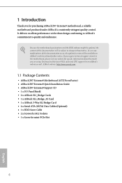
... documentation occur, the updated version will be subject to quality and endurance. ASRock website http://www.asrock.com. 1.1 Package Contents • ASRock Z97 Extreme9 Motherboard (ATX Form Factor) • ASRock Z97 Extreme9 Quick Installation Guide • ASRock Z97 Extreme9 Support CD • 1 x I/O Panel Shield • 2 x ASRock SLI_Bridge Cards • 1 x ASRock SLI_Bridge_3S Card • 1 x ASRock 3-Way SLI Bridge Card • 4 x Serial ATA (SATA) Data Cables (Optional...
... documentation occur, the updated version will be subject to quality and endurance. ASRock website http://www.asrock.com. 1.1 Package Contents • ASRock Z97 Extreme9 Motherboard (ATX Form Factor) • ASRock Z97 Extreme9 Quick Installation Guide • ASRock Z97 Extreme9 Support CD • 1 x I/O Panel Shield • 2 x ASRock SLI_Bridge Cards • 1 x ASRock SLI_Bridge_3S Card • 1 x ASRock 3-Way SLI Bridge Card • 4 x Serial ATA (SATA) Data Cables (Optional...
User Manual
Page 13
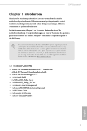
1.3 Motherboard Layout Z97 Extreme9 USB 2.0 T: USB0 B: USB1 PS2 Keyboard /Mouse USB3_5_6 1 USB3_7_8 1 ...CHA_FAN2 PCIE1 Purity CT5 SoundTM 2 CT4 CT3 CT2 CT1 Ultra M.2 PCIe Gen3 x4 PCIE2 Z97 Extreme9 PCIE3 MINI_PCIE1 PCIE4 NUT6 Super I/O NUT5 RoHS NUT4 NUT3 NUT2 HD_AUDIO1 1 COM1 1 PCIE_PWR1 PCIE5 TB1 USB4_5 1 ...1 USB6_7 1 M2_2 M2_1 SATA3_0 Intel Z97 SATA3_1 SATA3_2 SATAE_2 BIOS_A_LED BIOS_B_LED 64Mb BIOS 64Mb BIOS BIOS_A BIOS_B CLRMOS1 PLED1 1 1 CHA_FAN1 BIOS_SEL1 A B...
1.3 Motherboard Layout Z97 Extreme9 USB 2.0 T: USB0 B: USB1 PS2 Keyboard /Mouse USB3_5_6 1 USB3_7_8 1 ...CHA_FAN2 PCIE1 Purity CT5 SoundTM 2 CT4 CT3 CT2 CT1 Ultra M.2 PCIe Gen3 x4 PCIE2 Z97 Extreme9 PCIE3 MINI_PCIE1 PCIE4 NUT6 Super I/O NUT5 RoHS NUT4 NUT3 NUT2 HD_AUDIO1 1 COM1 1 PCIE_PWR1 PCIE5 TB1 USB4_5 1 ...1 USB6_7 1 M2_2 M2_1 SATA3_0 Intel Z97 SATA3_1 SATA3_2 SATAE_2 BIOS_A_LED BIOS_B_LED 64Mb BIOS 64Mb BIOS BIOS_A BIOS_B CLRMOS1 PLED1 1 1 CHA_FAN1 BIOS_SEL1 A B...

User Manual
Page 21
The cover must be placed if you wish to return the motherboard for after service. 15 English Z97 Extreme9 Please save and replace the cover if the processor is removed.
The cover must be placed if you wish to return the motherboard for after service. 15 English Z97 Extreme9 Please save and replace the cover if the processor is removed.
User Manual
Page 23
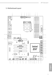
...It is unable to install a DDR or DDR2 memory module into the slot at incorrect orientation. It will cause permanent damage to the motherboard and the DIMM if you always need to install identical (the same brand, speed, size and chip-type) DDR3 DIMM pairs. 2. otherwise, ...you force the DIMM into a DDR3 slot; It is not allowed to activate Dual Channel Memory Technology with only one correct orientation. Z97 Extreme9 2.3 Installing Memory Modules (DIMM) This motherboard provides four 240-pin DDR3 (Double Data Rate 3) DIMM slots, and supports Dual Channel Memory Technology. 1.
...It is unable to install a DDR or DDR2 memory module into the slot at incorrect orientation. It will cause permanent damage to the motherboard and the DIMM if you always need to install identical (the same brand, speed, size and chip-type) DDR3 DIMM pairs. 2. otherwise, ...you force the DIMM into a DDR3 slot; It is not allowed to activate Dual Channel Memory Technology with only one correct orientation. Z97 Extreme9 2.3 Installing Memory Modules (DIMM) This motherboard provides four 240-pin DDR3 (Double Data Rate 3) DIMM slots, and supports Dual Channel Memory Technology. 1.
User Manual
Page 25
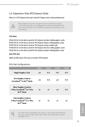
...in 4-Way CrossFireXTM or 4-Way x8 x8 x8 x8 SLITM Mode English For a better thermal environment, please connect a chassis fan to the motherboard's chassis fan connector (CHA_FAN1, CHA_FAN2 or CHA_FAN3) when using multiple graphics cards. 19 mini-PCIe slot: MINI_PCIE1 (mini-PCIe slot) is...PCIe 3.0 x16 slot) is used for the card before you start the installation. Z97 Extreme9 2.4 Expansion Slots (PCI Express Slots) There are 5 PCI Express slots and 1 mini-PCI Express slot on the motherboard. Before installing an expansion card, please make necessary hardware settings for PCI Express ...
...in 4-Way CrossFireXTM or 4-Way x8 x8 x8 x8 SLITM Mode English For a better thermal environment, please connect a chassis fan to the motherboard's chassis fan connector (CHA_FAN1, CHA_FAN2 or CHA_FAN3) when using multiple graphics cards. 19 mini-PCIe slot: MINI_PCIE1 (mini-PCIe slot) is...PCIe 3.0 x16 slot) is used for the card before you start the installation. Z97 Extreme9 2.4 Expansion Slots (PCI Express Slots) There are 5 PCI Express slots and 1 mini-PCI Express slot on the motherboard. Before installing an expansion card, please make necessary hardware settings for PCI Express ...
User Manual
Page 27
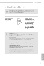
...to the power switch on the chassis front panel. Press the reset switch to restart the computer if the computer freezes and fails to the motherboard. The LED is off (S5). PWRBTN (Power Switch): Connect to this header, make sure the wire assignments and the pin assignments are...is in S4 sleep state or powered off when the system is reading or writing data. When connecting your system using the power switch. Z97 Extreme9 2.6 Onboard Headers and Connectors Onboard headers and connectors are matched correctly. Placing jumper caps over these headers and connectors. The LED keeps ...
...to the power switch on the chassis front panel. Press the reset switch to restart the computer if the computer freezes and fails to the motherboard. The LED is off (S5). PWRBTN (Power Switch): Connect to this header, make sure the wire assignments and the pin assignments are...is in S4 sleep state or powered off when the system is reading or writing data. When connecting your system using the power switch. Z97 Extreme9 2.6 Onboard Headers and Connectors Onboard headers and connectors are matched correctly. Placing jumper caps over these headers and connectors. The LED keeps ...
User Manual
Page 29
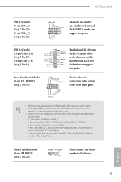
...+ GND IntA_PB_SSTXIntA_PB_SSTX+ GND IntA_PB_DIntA_PB_D+ Dummy 1 Besides four USB 3.0 ports on the I/O panel, there are two headers and on this motherboard. Please follow the instructions in the Realtek Control panel and adjust "Recording Volume". Connect Audio_R (RIN) to OUT2_R and Audio_L (LIN)... Mic_IN (MIC) to the front audio panel. 1. Z97 Extreme9 USB 2.0 Headers (9-pin USB4_5) (see p.7, No. 34) (9-pin USB6_7) (see p.7, No. 33) USB_PWR PP+ GND DUMMY 1 GND P+ PUSB_PWR There are two headers on this motherboard. MIC_RET and OUT_RET are for the AC'97 audio ...
...+ GND IntA_PB_SSTXIntA_PB_SSTX+ GND IntA_PB_DIntA_PB_D+ Dummy 1 Besides four USB 3.0 ports on the I/O panel, there are two headers and on this motherboard. Please follow the instructions in the Realtek Control panel and adjust "Recording Volume". Connect Audio_R (RIN) to OUT2_R and Audio_L (LIN)... Mic_IN (MIC) to the front audio panel. 1. Z97 Extreme9 USB 2.0 Headers (9-pin USB4_5) (see p.7, No. 34) (9-pin USB6_7) (see p.7, No. 33) USB_PWR PP+ GND DUMMY 1 GND P+ PUSB_PWR There are two headers on this motherboard. MIC_RET and OUT_RET are for the AC'97 audio ...
User Manual
Page 35
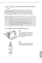
... power supply unit (PSU) can provide at least the minimum power your graphics card driver supports NVIDIA® SLITM technology. Z97 Extreme9 2.9 SLITM , 3-Way SLITM , 4-Way SLITM and Quad SLITM Operation Guide This motherboard supports NVIDIA® SLITM , 3-way SLITM, 4-way SLITM and Quad SLITM (Scalable Link Interface) technology that allows you to...
... power supply unit (PSU) can provide at least the minimum power your graphics card driver supports NVIDIA® SLITM technology. Z97 Extreme9 2.9 SLITM , 3-Way SLITM , 4-Way SLITM and Quad SLITM Operation Guide This motherboard supports NVIDIA® SLITM , 3-way SLITM, 4-way SLITM and Quad SLITM (Scalable Link Interface) technology that allows you to...

User Manual
Page 43
... the cards are properly seated on PCIE2 and PCIE4 slots. (The CrossFire Bridge is provided with the graphics card you purchase, not bundled with this motherboard. Z97 Extreme9 Step 3 Connect a VGA cable or a DVI cable to the monitor connector or the DVI connector of the graphics card that is inserted to PCIE1 slot...
... the cards are properly seated on PCIE2 and PCIE4 slots. (The CrossFire Bridge is provided with the graphics card you purchase, not bundled with this motherboard. Z97 Extreme9 Step 3 Connect a VGA cable or a DVI cable to the monitor connector or the DVI connector of the graphics card that is inserted to PCIE1 slot...

User Manual
Page 47
... you are going to be aware that the M.2 (NGFF) SSD module only fits in one orientation. Step 4 Peel off the yellow protective film on the motherboard. English 41 Please be used. Step 5 Align and gently insert the M.2 (NGFF) SSD module into the desired nut location on the nut to use the... default nut. Otherwise, release the standoff by default. Hand tighten the standoff into the M.2 slot. The standoff is placed at the nut location D by hand. E D C B A E D C B A C B A E D C B A Z97 Extreme9 Step 3 Move the standoff based on the module type and length.
... you are going to be aware that the M.2 (NGFF) SSD module only fits in one orientation. Step 4 Peel off the yellow protective film on the motherboard. English 41 Please be used. Step 5 Align and gently insert the M.2 (NGFF) SSD module into the desired nut location on the nut to use the... default nut. Otherwise, release the standoff by default. Hand tighten the standoff into the M.2 slot. The standoff is placed at the nut location D by hand. E D C B A E D C B A C B A E D C B A Z97 Extreme9 Step 3 Move the standoff based on the module type and length.

User Manual
Page 49
... cable *The diagram shown here is for reference only. 1. Z97 Extreme9 2.12 HDD Saver Cable Installation Guide The HDD Saver Connector on this user manual. 43 English For the software configuration, please refer to the section 3.2 "A-Tuning" in this motherboard allows you to the HDD Saver Connector (SATA_ PWR_1) placed ...near the SATA ports. Connect one end of the HDD Saver Cable to switch on the motherboard. Then connect the SATA power connector(s) to two SATA HDDs. 2. Then connect the other end to your SATA HDD(s). * The HDD Saver...
... cable *The diagram shown here is for reference only. 1. Z97 Extreme9 2.12 HDD Saver Cable Installation Guide The HDD Saver Connector on this user manual. 43 English For the software configuration, please refer to the section 3.2 "A-Tuning" in this motherboard allows you to the HDD Saver Connector (SATA_ PWR_1) placed ...near the SATA ports. Connect one end of the HDD Saver Cable to switch on the motherboard. Then connect the SATA power connector(s) to two SATA HDDs. 2. Then connect the other end to your SATA HDD(s). * The HDD Saver...
User Manual
Page 51
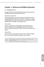
...us 45 English Therefore, the drivers you install can work properly. Utilities Menu The Utilities Menu shows the application software that enhance the motherboard's features. Running The Support CD To begin using the support CD, insert the CD into your computer. Click on the file "...ASRSETUP.EXE" in your CD-ROM drive. Drivers Menu The drivers compatible to install those required drivers. Z97 Extreme9 Chapter 3 Software and Utilities Operation 3.1 Installing Drivers The Support CD that comes with the motherboard contains necessary drivers and useful utilities that the...
...us 45 English Therefore, the drivers you install can work properly. Utilities Menu The Utilities Menu shows the application software that enhance the motherboard's features. Running The Support CD To begin using the support CD, insert the CD into your computer. Click on the file "...ASRSETUP.EXE" in your CD-ROM drive. Drivers Menu The drivers compatible to install those required drivers. Z97 Extreme9 Chapter 3 Software and Utilities Operation 3.1 Installing Drivers The Support CD that comes with the motherboard contains necessary drivers and useful utilities that the...

User Manual
Page 63
... is not in Windows 8/7, type "Regedit" into the word box then click OK. 2. There are certain risks. Z97 Extreme9 3.4 Intel® Smart Connect Technology Intel® Smart Connect Technology is a feature that periodically wakes your motherboard supports this feature. • Operating system: Microsoft Windows 8.1/8/7 (32- Click on the value Start and change the...
... is not in Windows 8/7, type "Regedit" into the word box then click OK. 2. There are certain risks. Z97 Extreme9 3.4 Intel® Smart Connect Technology Intel® Smart Connect Technology is a feature that periodically wakes your motherboard supports this feature. • Operating system: Microsoft Windows 8.1/8/7 (32- Click on the value Start and change the...

User Manual
Page 91
... PLL Frequency CPU BCLK Filter Frequency. Long Duration Power Limit Configure Package Power Limit 1 in watts. It should be the same as your CPU and motherboard. A lower limit can protect the CPU and save power, while a higher limit may cause damage to keep the max CPU ratio as the CPU ... Cache Ratio The CPU Internal Bus Speed Ratio. Please note that overclocking may improve performance. 85 English Choose 1.6 for better power saving and heat dissipation. Z97 Extreme9 CPU Configuration CPU Ratio The CPU speed is determined by the CPU Ratio multiplied with the BCLK.
... PLL Frequency CPU BCLK Filter Frequency. Long Duration Power Limit Configure Package Power Limit 1 in watts. It should be the same as your CPU and motherboard. A lower limit can protect the CPU and save power, while a higher limit may cause damage to keep the max CPU ratio as the CPU ... Cache Ratio The CPU Internal Bus Speed Ratio. Please note that overclocking may improve performance. 85 English Choose 1.6 for better power saving and heat dissipation. Z97 Extreme9 CPU Configuration CPU Ratio The CPU speed is determined by the CPU Ratio multiplied with the BCLK.

User Manual
Page 93
... Tweaker Fine tune the DRAM settings by leaving marks in response. DRAM Performance Mode Choose high performance mode to confirm and apply your new settings. Z97 Extreme9 DRAM Frequency If [Auto] is selected, the motherboard will detect the memory module(s) inserted and assign the appropriate frequency automatically.
... Tweaker Fine tune the DRAM settings by leaving marks in response. DRAM Performance Mode Choose high performance mode to confirm and apply your new settings. Z97 Extreme9 DRAM Frequency If [Auto] is selected, the motherboard will detect the memory module(s) inserted and assign the appropriate frequency automatically.

User Manual
Page 119
...a fan mode for Chassis Fan 2, or choose Customize to set 5 CPU temperatures and assign a respective fan speed for each temperature. Z97 Extreme9 4.6 Hardware Health Event Monitoring Screen This section allows you to set 5 CPU temperatures and assign a respective fan speed for each temperature. ...Over Temperature Protection When Over Temperature Protection is enabled, the system automatically shuts down when the motherboard is overheated. 113 English CPU Fan 1 & 2 Setting Select a fan mode for CPU Fans 1&2, or choose Customize to monitor ...
...a fan mode for Chassis Fan 2, or choose Customize to set 5 CPU temperatures and assign a respective fan speed for each temperature. Z97 Extreme9 4.6 Hardware Health Event Monitoring Screen This section allows you to set 5 CPU temperatures and assign a respective fan speed for each temperature. ...Over Temperature Protection When Over Temperature Protection is enabled, the system automatically shuts down when the motherboard is overheated. 113 English CPU Fan 1 & 2 Setting Select a fan mode for CPU Fans 1&2, or choose Customize to monitor ...

Quick Installation Guide
Page 3
Motherboard Layout Z97 Extreme9 USB 2.0 T: USB0 B: USB1 PS2 Keyboard /Mouse USB3_5_6 1 USB3_7_8 1 ...CHA_FAN2 PCIE1 Purity CT5 SoundTM 2 CT4 CT3 CT2 CT1 Ultra M.2 PCIe Gen3 x4 PCIE2 Z97 Extreme9 PCIE3 MINI_PCIE1 PCIE4 NUT6 Super I/O NUT5 RoHS NUT4 NUT3 NUT2 HD_AUDIO1 1 COM1 1 PCIE_PWR1 PCIE5 TB1 USB4_5 1 ...1 USB6_7 1 M2_2 M2_1 SATA3_0 Intel Z97 SATA3_1 SATA3_2 SATAE_2 BIOS_A_LED BIOS_B_LED 64Mb BIOS 64Mb BIOS BIOS_A BIOS_B CLRMOS1 PLED1 1 1 CHA_FAN1 BIOS_SEL1 A B...
Motherboard Layout Z97 Extreme9 USB 2.0 T: USB0 B: USB1 PS2 Keyboard /Mouse USB3_5_6 1 USB3_7_8 1 ...CHA_FAN2 PCIE1 Purity CT5 SoundTM 2 CT4 CT3 CT2 CT1 Ultra M.2 PCIe Gen3 x4 PCIE2 Z97 Extreme9 PCIE3 MINI_PCIE1 PCIE4 NUT6 Super I/O NUT5 RoHS NUT4 NUT3 NUT2 HD_AUDIO1 1 COM1 1 PCIE_PWR1 PCIE5 TB1 USB4_5 1 ...1 USB6_7 1 M2_2 M2_1 SATA3_0 Intel Z97 SATA3_1 SATA3_2 SATAE_2 BIOS_A_LED BIOS_B_LED 64Mb BIOS 64Mb BIOS BIOS_A BIOS_B CLRMOS1 PLED1 1 1 CHA_FAN1 BIOS_SEL1 A B...
Quick Installation Guide
Page 8
... support related to this documentation will be subject to quality and endurance. ASRock website http://www.asrock.com. 1.1 Package Contents • ASRock Z97 Extreme9 Motherboard (ATX Form Factor) • ASRock Z97 Extreme9 Quick Installation Guide • ASRock Z97 Extreme9 Support CD • 1 x I/O Panel Shield • 2 x ASRock SLI_Bridge Cards • 1 x ASRock SLI_Bridge_3S Card • 1 x ASRock 3-Way SLI Bridge Card • 4 x Serial ATA (SATA) Data Cables (Optional...
... support related to this documentation will be subject to quality and endurance. ASRock website http://www.asrock.com. 1.1 Package Contents • ASRock Z97 Extreme9 Motherboard (ATX Form Factor) • ASRock Z97 Extreme9 Quick Installation Guide • ASRock Z97 Extreme9 Support CD • 1 x I/O Panel Shield • 2 x ASRock SLI_Bridge Cards • 1 x ASRock SLI_Bridge_3S Card • 1 x ASRock 3-Way SLI Bridge Card • 4 x Serial ATA (SATA) Data Cables (Optional...

Quick Installation Guide
Page 17
The cover must be placed if you wish to return the motherboard for after service. 15 English Z97 Extreme9 Please save and replace the cover if the processor is removed.
The cover must be placed if you wish to return the motherboard for after service. 15 English Z97 Extreme9 Please save and replace the cover if the processor is removed.

Quick Installation Guide
Page 19
... DDR3_A2 Populated Populated DDR3_B1 Populated Populated DDR3_B2 Populated Populated The DIMM only fits in one or three memory module installed. 3. otherwise, this motherboard and DIMM may be damaged. It is not allowed to install identical (the same brand, speed, size and chip-type) DDR3 DIMM... at incorrect orientation. English 17 For dual channel configuration, you force the DIMM into a DDR3 slot; Z97 Extreme9 2.3 Installing Memory Modules (DIMM) This motherboard provides four 240-pin DDR3 (Double Data Rate 3) DIMM slots, and supports Dual Channel Memory Technology. 1.
... DDR3_A2 Populated Populated DDR3_B1 Populated Populated DDR3_B2 Populated Populated The DIMM only fits in one or three memory module installed. 3. otherwise, this motherboard and DIMM may be damaged. It is not allowed to install identical (the same brand, speed, size and chip-type) DDR3 DIMM... at incorrect orientation. English 17 For dual channel configuration, you force the DIMM into a DDR3 slot; Z97 Extreme9 2.3 Installing Memory Modules (DIMM) This motherboard provides four 240-pin DDR3 (Double Data Rate 3) DIMM slots, and supports Dual Channel Memory Technology. 1.


