
Intel Rapid Storage Guide
Page 12
...Storage Technology option ROM status screen appears during operating system setup. Select 1: Create RAID Volume and press Enter. 3. Press Enter to enter the BIOS Setup program after the Power-On-Self-Test (POST) memory test begins. 2. Click the Storage Configuration menu. 4. Click F2 or Delete ...to select the physical disks. 6. Switch the SATA Operation Mode option to save the BIOS settings and exit the BIOS Setup program. Select the appropriate number of hard drives and press Space to select the drive. The F6 installation method is not...
...Storage Technology option ROM status screen appears during operating system setup. Select 1: Create RAID Volume and press Enter. 3. Press Enter to enter the BIOS Setup program after the Power-On-Self-Test (POST) memory test begins. 2. Click the Storage Configuration menu. 4. Click F2 or Delete ...to select the physical disks. 6. Switch the SATA Operation Mode option to save the BIOS settings and exit the BIOS Setup program. Select the appropriate number of hard drives and press Space to select the drive. The F6 installation method is not...
RAID Installation Guide
Page 1
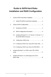
...; 8.1 / 8.1 64-bit / 8 / 8 64-bit / 7 / 7 64-bit With RAID Functions 7 2.4 Configuring a RAID array 8 2.4.1 Configuring a RAID array Using UEFI Setup Utility....... 9 2.4.2 Configuring a RAID array Using Intel RAID BIOS....... 13 3. Installing Windows® on a HDD under 2TB in RAID mode 18 1 Guide to SATA Hard Disks Installation 2 1.1 Serial ATA (SATA) Hard Disks Installation 2 2. Installing...
...; 8.1 / 8.1 64-bit / 8 / 8 64-bit / 7 / 7 64-bit With RAID Functions 7 2.4 Configuring a RAID array 8 2.4.1 Configuring a RAID array Using UEFI Setup Utility....... 9 2.4.2 Configuring a RAID array Using Intel RAID BIOS....... 13 3. Installing Windows® on a HDD under 2TB in RAID mode 18 1 Guide to SATA Hard Disks Installation 2 1.1 Serial ATA (SATA) Hard Disks Installation 2 2. Installing...
RAID Installation Guide
Page 7
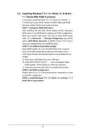
STEP 2: Use ASRock Easy RAID Installer Easy RAID Installer can copy the RAID driver from a support CD to save... the selection C. Press [Enter] to [RAID]. STEP 1: Setting the BIOS RAID Items After installing the hard disk drives, please set RAID configuration. Plug in the BIOS before you want to enter BIOS setup utility. STEP 3: Set RAID configuration Please refer to p.8 -17 ...2.3 Installing Windows® 8.1 / 8.1 64-bit / 8 / 8 64-bit / 7 / 7 64-bit With RAID Functions If you exit BIOS setup. Boot your SATA / SATA2 / SATA3 HDDs with just one simple click in UEFI setup.
STEP 2: Use ASRock Easy RAID Installer Easy RAID Installer can copy the RAID driver from a support CD to save... the selection C. Press [Enter] to [RAID]. STEP 1: Setting the BIOS RAID Items After installing the hard disk drives, please set RAID configuration. Plug in the BIOS before you want to enter BIOS setup utility. STEP 3: Set RAID configuration Please refer to p.8 -17 ...2.3 Installing Windows® 8.1 / 8.1 64-bit / 8 / 8 64-bit / 7 / 7 64-bit With RAID Functions If you exit BIOS setup. Boot your SATA / SATA2 / SATA3 HDDs with just one simple click in UEFI setup.
RAID Installation Guide
Page 8
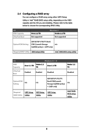
...Setting UEFI SETUP UTILITY\Boot\ CSM [Launch Storage n/a OpROM policy] = [UEFI only] Required RAID Utility UEFI Setup Utility Intel® RAID BIOS setup utility OS HDD Capacity Ultra Fast Boot Windows 8.1 / 8 Under 2.2 Over 2.2 TB TB Over 2.2 TB Enabled Enabled Disabled Under 2.2 ...n/a Setting Storage OpROM policy] = [UEFI only] Required UEFI Setup UEFI Setup UEFI Setup RAID Utility Utility Utility Utility Intel® RAID BIOS setup utility 8 Please refer to the table below to choose the corresponding RAID Utility. 2.4 Configuring a RAID array You can configure a RAID...
...Setting UEFI SETUP UTILITY\Boot\ CSM [Launch Storage n/a OpROM policy] = [UEFI only] Required RAID Utility UEFI Setup Utility Intel® RAID BIOS setup utility OS HDD Capacity Ultra Fast Boot Windows 8.1 / 8 Under 2.2 Over 2.2 TB TB Over 2.2 TB Enabled Enabled Disabled Under 2.2 ...n/a Setting Storage OpROM policy] = [UEFI only] Required UEFI Setup UEFI Setup UEFI Setup RAID Utility Utility Utility Utility Intel® RAID BIOS setup utility 8 Please refer to the table below to choose the corresponding RAID Utility. 2.4 Configuring a RAID array You can configure a RAID...
RAID Installation Guide
Page 13
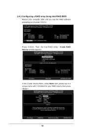
Press . Create RAID Volume window appears. Volume0 13 Wait until you see the RAID software prompting you to press . Then, the Intel RAID Utility - In the Create Volume Menu, under Name item, please key-in a unique name with 1-16 letters for your computer. 2.4.2 Configuring a RAID array Using Intel RAID BIOS Reboot your RAID volume then press .
Press . Create RAID Volume window appears. Volume0 13 Wait until you see the RAID software prompting you to press . Then, the Intel RAID Utility - In the Create Volume Menu, under Name item, please key-in a unique name with 1-16 letters for your computer. 2.4.2 Configuring a RAID array Using Intel RAID BIOS Reboot your RAID volume then press .
RAID Installation Guide
Page 16
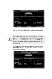
Please note that you want to configure RAID functions after you are only allowed to complete the setup of RAID. Press to create one RAID partition at a time under Windows environment to delete a RAID volume, please select the option Delete RAID Volume, press , and then follow the instructions on the screen. 16 If you set up. After the completion, you will see the detailed information about the RAID that you install OS. If you want to create an extra RAID partition, please use the RAID utility under BIOS RAID environment.
Please note that you want to configure RAID functions after you are only allowed to complete the setup of RAID. Press to create one RAID partition at a time under Windows environment to delete a RAID volume, please select the option Delete RAID Volume, press , and then follow the instructions on the screen. 16 If you set up. After the completion, you will see the detailed information about the RAID that you install OS. If you want to create an extra RAID partition, please use the RAID utility under BIOS RAID environment.
RAID Installation Guide
Page 17
Installing Windows® on a HDD under 2TB in RAID mode After the UEFI and RAID BIOS setup you may start installing Windows® 8.1 / 8.1 64-bit / 8 / 8 64-bit / 7 / 7 64-bit OS as usual. 17 3.
Installing Windows® on a HDD under 2TB in RAID mode After the UEFI and RAID BIOS setup you may start installing Windows® 8.1 / 8.1 64-bit / 8 / 8 64-bit / 7 / 7 64-bit OS as usual. 17 3.
RAID Installation Guide
Page 18
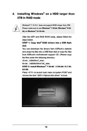
4. After the UEFI and RAID BIOS setup, please follow the steps below. Installing Windows® on a HDD larger than 2TB in RAID mode Windows® 7 / 8 / 8.1 does not support HDD's larger than ...; 8.1 64-bit. STEP 1: Copy Intel® RAID drivers into a USB flash disk You can download the drivers from ASRock's website and unzip the files into a USB flash disk or copy the files from ASRock's motherboard support CD. (Please copy the files under the following directory: 32 bit: ..\i386\Win7_Intel.. 64-bit: ..\AMD64...
4. After the UEFI and RAID BIOS setup, please follow the steps below. Installing Windows® on a HDD larger than 2TB in RAID mode Windows® 7 / 8 / 8.1 does not support HDD's larger than ...; 8.1 64-bit. STEP 1: Copy Intel® RAID drivers into a USB flash disk You can download the drivers from ASRock's website and unzip the files into a USB flash disk or copy the files from ASRock's motherboard support CD. (Please copy the files under the following directory: 32 bit: ..\i386\Win7_Intel.. 64-bit: ..\AMD64...

Quick Installation Guide
Page 3
... REAR SPK Bottom: Optical SPDIF CHA_FAN3 CHA_FAN2 PCIE_PWR1 TPMS1 7 Top: Center: FRONT Bottom: MIC IN 33 PCIE1 1 Purity SoundTM 2 Z97 Extreme4 PCIE2 32 8 9 CHA_FAN1 10 SATA3_A1 SATA3_A0 1 SATA_PWR_1 11 12 SATA3_3 SATA3_0 PCIE3 13 14 PCIE4 CMOS Battery 31 1 HD_AUDIO1 PCIE5 Intel SATA3_1 SATA3_4...NUT1 RoHS PCIE6 PWR_FAN1 CLRMOS1 1 USB2_3 1 USB4_5 1 SPEAKER1 1 1 PLED1 PLED PWRBTN 1 HDLED RESET PANEL1 Dr. Debug BIOS_SEL1 A B 64Mb BIOS BIOS_B 64Mb BIOS BIOS_A BIOS_B_LED BIOS_A_LED CLRCBTN1 Reset Power 19 30 29 28 27 26 25 24 23 22 21 20 English 1
... REAR SPK Bottom: Optical SPDIF CHA_FAN3 CHA_FAN2 PCIE_PWR1 TPMS1 7 Top: Center: FRONT Bottom: MIC IN 33 PCIE1 1 Purity SoundTM 2 Z97 Extreme4 PCIE2 32 8 9 CHA_FAN1 10 SATA3_A1 SATA3_A0 1 SATA_PWR_1 11 12 SATA3_3 SATA3_0 PCIE3 13 14 PCIE4 CMOS Battery 31 1 HD_AUDIO1 PCIE5 Intel SATA3_1 SATA3_4...NUT1 RoHS PCIE6 PWR_FAN1 CLRMOS1 1 USB2_3 1 USB4_5 1 SPEAKER1 1 1 PLED1 PLED PWRBTN 1 HDLED RESET PANEL1 Dr. Debug BIOS_SEL1 A B 64Mb BIOS BIOS_B 64Mb BIOS BIOS_A BIOS_B_LED BIOS_A_LED CLRCBTN1 Reset Power 19 30 29 28 27 26 25 24 23 22 21 20 English 1
Quick Installation Guide
Page 4
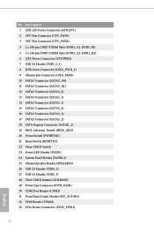
... SATA3 Connector (SATA3_3) 14 SATA3 Connector (SATA3_1) 15 SATA3 Connector (SATA3_4) 16 SATA3 Connector (SATA3_2) 17 SATA3 Connector (SATA3_5) 18 SATA Express Connector (SATAE_1) 19 BIOS Selection Switch (BIOS_SEL1) 20 Power Switch (PWRBTN1) 21 Reset Switch (RSTBTN1) 22 Clear CMOS Switch 23 Power LED Header (PLED1) 24 System Panel Header (PANEL1...
... SATA3 Connector (SATA3_3) 14 SATA3 Connector (SATA3_1) 15 SATA3 Connector (SATA3_4) 16 SATA3 Connector (SATA3_2) 17 SATA3 Connector (SATA3_5) 18 SATA Express Connector (SATAE_1) 19 BIOS Selection Switch (BIOS_SEL1) 20 Power Switch (PWRBTN1) 21 Reset Switch (RSTBTN1) 22 Clear CMOS Switch 23 Power LED Header (PLED1) 24 System Panel Header (PANEL1...
Quick Installation Guide
Page 8
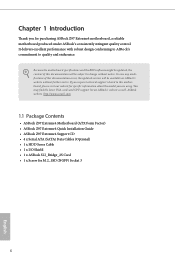
Because the motherboard specifications and the BIOS software might be updated, the content of this documentation occur, the updated version will be available on ASRock's website as well. ASRock website http://www.asrock.com. 1.1 Package Contents • ASRock Z97 Extreme4 Motherboard (ATX Form Factor) • ASRock Z97 Extreme4 Quick Installation Guide • ASRock Z97 Extreme4 Support CD • 4 x Serial ATA (SATA) Data Cables (Optional...
Because the motherboard specifications and the BIOS software might be updated, the content of this documentation occur, the updated version will be available on ASRock's website as well. ASRock website http://www.asrock.com. 1.1 Package Contents • ASRock Z97 Extreme4 Motherboard (ATX Form Factor) • ASRock Z97 Extreme4 Quick Installation Guide • ASRock Z97 Extreme4 Support CD • 4 x Serial ATA (SATA) Data Cables (Optional...
Quick Installation Guide
Page 12
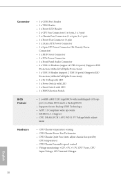
... Audio Connector • 2 x USB 2.0 Headers (support 4 USB 2.0 ports) (Supports ESD Protection (ASRock Full Spike Protection)) • 1 x USB 3.0 Header (support 2 USB 3.0 ports) (Supports ESD Protection (ASRock Full Spike Protection)) • 1 x Dr. Debug with LED • 1 x Power Switch with LED... • 1 x Reset Switch with LED • 1 x BIOS Selection Switch BIOS Feature • 2 x 64Mb AMI UEFI Legal BIOS with multilingual GUI support (1 x Main BIOS and 1 x Backup BIOS) &#...
... Audio Connector • 2 x USB 2.0 Headers (support 4 USB 2.0 ports) (Supports ESD Protection (ASRock Full Spike Protection)) • 1 x USB 3.0 Header (support 2 USB 3.0 ports) (Supports ESD Protection (ASRock Full Spike Protection)) • 1 x Dr. Debug with LED • 1 x Power Switch with LED... • 1 x Reset Switch with LED • 1 x BIOS Selection Switch BIOS Feature • 2 x 64Mb AMI UEFI Legal BIOS with multilingual GUI support (1 x Main BIOS and 1 x Backup BIOS) &#...
Quick Installation Guide
Page 13
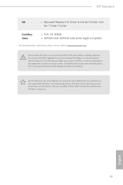
Z97 Extreme4 OS • Microsoft® Windows® 8.1 32-bit / 8.1 64-bit / 8 32-bit / 8 64- bit / 7 32-bit / 7 64-bit Certifications • FCC, CE, WHQL • ErP/EuP ready (ErP/EuP ready power supply is required) * For detailed product information, please visit our website: http://www.asrock.com Please realize that ..., or even cause damage to utilize the memory that there is a certain risk involved with overclocking, including adjusting the setting in the BIOS, applying Untied Overclocking Technology, or using third-party overclocking tools. English 11
Z97 Extreme4 OS • Microsoft® Windows® 8.1 32-bit / 8.1 64-bit / 8 32-bit / 8 64- bit / 7 32-bit / 7 64-bit Certifications • FCC, CE, WHQL • ErP/EuP ready (ErP/EuP ready power supply is required) * For detailed product information, please visit our website: http://www.asrock.com Please realize that ..., or even cause damage to utilize the memory that there is a certain risk involved with overclocking, including adjusting the setting in the BIOS, applying Untied Overclocking Technology, or using third-party overclocking tools. English 11
Quick Installation Guide
Page 22
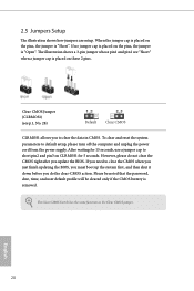
... reset the system parameters to clear the data in CMOS. Clear CMOS Jumper (CLRMOS1) (see p.1, No. 28) Default Clear CMOS CLRMOS1 allows you update the BIOS. Please be noted that the password, date, time, and user default profile will be cleared only if the CMOS battery is "Short". When the jumper... jumpers are "Short" when a jumper cap is placed on CLRMOS1 for 5 seconds. If you need to clear the CMOS when you just finish updating the BIOS, you must boot up the system first, and then shut it down before you do not clear the CMOS right after you to default setup...
... reset the system parameters to clear the data in CMOS. Clear CMOS Jumper (CLRMOS1) (see p.1, No. 28) Default Clear CMOS CLRMOS1 allows you update the BIOS. Please be noted that the password, date, time, and user default profile will be cleared only if the CMOS battery is "Short". When the jumper... jumpers are "Short" when a jumper cap is placed on CLRMOS1 for 5 seconds. If you need to clear the CMOS when you just finish updating the BIOS, you must boot up the system first, and then shut it down before you do not clear the CMOS right after you to default setup...
Quick Installation Guide
Page 28
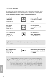
...quickly turn on the primary BIOS. This motherboard has two BIOS chips, a primary BIOS (BIOS_A) and a backup BIOS (BIOS_ B), which BIOS is currently activated. Clear CMOS Switch (CLRCBTN1) (see p.1 No. 19) AB BIOS Selection Switch allows the system to "B", then the backup BIOS will work on /off...the system, reset the system, clear the CMOS values or boot from either BIOS A or BIOS B. 2.7 Smart Switches The motherboard has four smart switches: Power Switch, Reset Switch, Clear CMOS Switch and BIOS Selection Switch, allowing users to quickly reset the system. Reset Switch (RSTBTN1)...
...quickly turn on the primary BIOS. This motherboard has two BIOS chips, a primary BIOS (BIOS_A) and a backup BIOS (BIOS_ B), which BIOS is currently activated. Clear CMOS Switch (CLRCBTN1) (see p.1 No. 19) AB BIOS Selection Switch allows the system to "B", then the backup BIOS will work on /off...the system, reset the system, clear the CMOS values or boot from either BIOS A or BIOS B. 2.7 Smart Switches The motherboard has four smart switches: Power Switch, Reset Switch, Clear CMOS Switch and BIOS Selection Switch, allowing users to quickly reset the system. Reset Switch (RSTBTN1)...
Quick Installation Guide
Page 131
Z97 Extreme4 인증 • FCC, CE, WHQL • ErP/EuP ErP/EuP http://www.asrock.com BIOS Untied Overclocking Technology Windows® 32 4GB Windows® 64 ASRock XFast RAM Windows 한국어 129
Z97 Extreme4 인증 • FCC, CE, WHQL • ErP/EuP ErP/EuP http://www.asrock.com BIOS Untied Overclocking Technology Windows® 32 4GB Windows® 64 ASRock XFast RAM Windows 한국어 129
Quick Installation Guide
Page 138
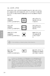
1.5 CMOS BIOS CMOS BIOS (PWRBTN1) (1 20 (RSTBTN1) (1 21 RESET CMOS CLRCBTN1) (1 22 CMOS CMOS 다. 한 국 어 BIOS BIOS_SEL1) (1 19 AB BIOS BIOS A 또는 BIOS B BIOS BIOS (BIOS_A BIOS (BIOS_B BIOS BIOS BIOS B BIOS UEFI Setup Utility 에서 "Secure Backup UEFI UEFI BIOS BIOS BIOS BIOS LED (BIOS_A_LED 또는 BIOS_B_LED BIOS 136
1.5 CMOS BIOS CMOS BIOS (PWRBTN1) (1 20 (RSTBTN1) (1 21 RESET CMOS CLRCBTN1) (1 22 CMOS CMOS 다. 한 국 어 BIOS BIOS_SEL1) (1 19 AB BIOS BIOS A 또는 BIOS B BIOS BIOS (BIOS_A BIOS (BIOS_B BIOS BIOS BIOS B BIOS UEFI Setup Utility 에서 "Secure Backup UEFI UEFI BIOS BIOS BIOS BIOS LED (BIOS_A_LED 또는 BIOS_B_LED BIOS 136
Quick Installation Guide
Page 164
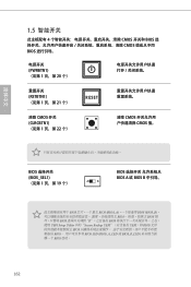
简体中文 1.5 4 CMOS 开关和 BIOS CMOS BIOS PWRBTN1) (见第 1 页,第 20 个) RSTBTN1) &#...38500; CMOS CMOS 值。 BIOS BIOS_SEL1) (见第 1 页,第 19 个) AB BIOS BIOS A 或 BIOS B BIOS BIOS (BIOS_A BIOS (BIOS_B BIOS BIOS BIOS B BIOS UEFI Setup Utility 中的"Secure Backup UEFI UEFI)将 BIOS BIOS BIOS BIOS LED (BIOS_A_LED 或 BIOS_B_LED BIOS 启动。 162
简体中文 1.5 4 CMOS 开关和 BIOS CMOS BIOS PWRBTN1) (见第 1 页,第 20 个) RSTBTN1) &#...38500; CMOS CMOS 值。 BIOS BIOS_SEL1) (见第 1 页,第 19 个) AB BIOS BIOS A 或 BIOS B BIOS BIOS (BIOS_A BIOS (BIOS_B BIOS BIOS BIOS B BIOS UEFI Setup Utility 中的"Secure Backup UEFI UEFI)将 BIOS BIOS BIOS BIOS LED (BIOS_A_LED 或 BIOS_B_LED BIOS 启动。 162
Quick Installation Guide
Page 170
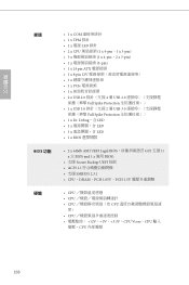
繁體中文 接頭 BIOS • 1 x COM 1 x TPM 排針 • 1 x 電源 LED 排針 • 2 x CPU 1 x 4-pin、1 x 3-pin) • 3 x 1 x 4-pin、2 x 3-pin)... 3.0 Full Spike Protection 1 x Dr. Debug,含 LED • 1 x LED • 1 x LED • 1 x BIOS • 2 x 64Mb AMI UEFI Legal BIOS GUI 支援 (1 x 主 BIOS and 1 x 備用 BIOS) • 支援 Secure Backup UEFI 技術 • ACPI 1.1 SMBIOS 2.3.1 • CPU、DRAM、PCH 1.05V&#...
繁體中文 接頭 BIOS • 1 x COM 1 x TPM 排針 • 1 x 電源 LED 排針 • 2 x CPU 1 x 4-pin、1 x 3-pin) • 3 x 1 x 4-pin、2 x 3-pin)... 3.0 Full Spike Protection 1 x Dr. Debug,含 LED • 1 x LED • 1 x LED • 1 x BIOS • 2 x 64Mb AMI UEFI Legal BIOS GUI 支援 (1 x 主 BIOS and 1 x 備用 BIOS) • 支援 Secure Backup UEFI 技術 • ACPI 1.1 SMBIOS 2.3.1 • CPU、DRAM、PCH 1.05V&#...


