
Intel Smart Response Installation Guide
Page 1
For the new version RST driver, please check our website for the latest information: http://www.asrock.com * Before you use RST function, you just need to set the UEFI option "SATA Mode" to show the newly accelerated system configuration. * Intel® ... system setup, including installing the OS to a RAID mode system, then install all performance testing, chose "Maximized" mode. 7. Intel Smart Response Technology Installation Guide This motherboard supports Intel Smart Response Technology.
For the new version RST driver, please check our website for the latest information: http://www.asrock.com * Before you use RST function, you just need to set the UEFI option "SATA Mode" to show the newly accelerated system configuration. * Intel® ... system setup, including installing the OS to a RAID mode system, then install all performance testing, chose "Maximized" mode. 7. Intel Smart Response Technology Installation Guide This motherboard supports Intel Smart Response Technology.

Intel Rapid Storage Guide
Page 12
... or down arrow keys to select the physical disks. 6. When finished press Enter. 12 Enable RAID in System BIOS Use the instructions included with your motherboard to enable RAID in the system BIOS, a RAID volume must be created, and the F6 installation method must be enabled in the system BIOS. 1. Click...
... or down arrow keys to select the physical disks. 6. When finished press Enter. 12 Enable RAID in System BIOS Use the instructions included with your motherboard to enable RAID in the system BIOS, a RAID volume must be created, and the F6 installation method must be enabled in the system BIOS. 1. Click...
RAID Installation Guide
Page 2
You may install SATA hard disks on SATA ports. 2 This section will guide you how to create RAID on this guide carefully according to SATA Hard Disks Installation 1.1 Serial ATA (SATA) Hard Disks Installation Intel chipset supports Serial ATA (SATA) hard disks with RAID functions, including RAID 0, RAID 1, RAID 5, RAID 10 and Intel Rapid Storage. Please read the RAID configurations in this motherboard for internal storage devices. Guide to the Intel southbridge chipset that your motherboard adopts. 1.
You may install SATA hard disks on SATA ports. 2 This section will guide you how to create RAID on this guide carefully according to SATA Hard Disks Installation 1.1 Serial ATA (SATA) Hard Disks Installation Intel chipset supports Serial ATA (SATA) hard disks with RAID functions, including RAID 0, RAID 1, RAID 5, RAID 10 and Intel Rapid Storage. Please read the RAID configurations in this motherboard for internal storage devices. Guide to the Intel southbridge chipset that your motherboard adopts. 1.
RAID Installation Guide
Page 3
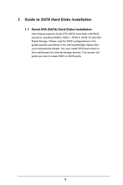
... identical hard disk drives to the surviving drive as a single drive but at a sustained data transfer rate. Guide to RAID Configurations 2.1 Introduction of RAID This motherboard adopts Intel southbridge chipset that copies and maintains an identical image of data from one drive to configure RAID 0 / RAID 1/ Intel Rapid Storage / RAID 10...
... identical hard disk drives to the surviving drive as a single drive but at a sustained data transfer rate. Guide to RAID Configurations 2.1 Introduction of RAID This motherboard adopts Intel southbridge chipset that copies and maintains an identical image of data from one drive to configure RAID 0 / RAID 1/ Intel Rapid Storage / RAID 10...
RAID Installation Guide
Page 18
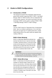
... steps below. STEP 1: Copy Intel® RAID drivers into a USB flash disk You can download the drivers from ASRock's website and unzip the files into a USB flash disk or copy the files from ASRock's motherboard support CD. (Please copy the files under the following directory: 32 bit: ..\i386\Win7_Intel.. 64-bit: ..\AMD64\Win7...
... steps below. STEP 1: Copy Intel® RAID drivers into a USB flash disk You can download the drivers from ASRock's website and unzip the files into a USB flash disk or copy the files from ASRock's motherboard support CD. (Please copy the files under the following directory: 32 bit: ..\i386\Win7_Intel.. 64-bit: ..\AMD64\Win7...
RAID Installation Guide
Page 20
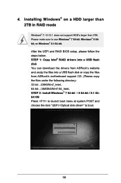
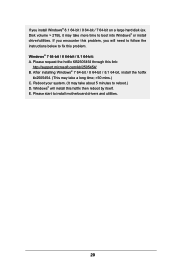
... then reboot by itself. After installing Windows® 7 64-bit / 8 64-bit / 8.1 64-bit, install the hotfix kb2505454. (This may take about 5 minutes to install motherboard drivers and utilities. 20 Windows® will need to follow the instructions below to fix this problem. E. Please start to reboot.) D. Reboot your system. (It...
... then reboot by itself. After installing Windows® 7 64-bit / 8 64-bit / 8.1 64-bit, install the hotfix kb2505454. (This may take about 5 minutes to install motherboard drivers and utilities. 20 Windows® will need to follow the instructions below to fix this problem. E. Please start to reboot.) D. Reboot your system. (It...

User Manual
Page 2
... you discard the Lithium battery in California, USA, please follow the related regulations in Perchlorate Best Management Practices (BMP) regulations passed by ASRock. ASRock assumes no event shall ASRock, its directors, officers, employees, or agents be constructed as a commitment by the California Legislature. Operation is subject to the following two... FCC Rules. CALIFORNIA, USA ONLY The Lithium battery adopted on this documentation. "Perchlorate Material-special handling may appear in this motherboard contains Perchlorate, a toxic substance controlled in advance.
... you discard the Lithium battery in California, USA, please follow the related regulations in Perchlorate Best Management Practices (BMP) regulations passed by ASRock. ASRock assumes no event shall ASRock, its directors, officers, employees, or agents be constructed as a commitment by the California Legislature. Operation is subject to the following two... FCC Rules. CALIFORNIA, USA ONLY The Lithium battery adopted on this documentation. "Perchlorate Material-special handling may appear in this motherboard contains Perchlorate, a toxic substance controlled in advance.

User Manual
Page 4
Contents Chapter 1 Introduction 1 1.1 Package Contents 1 1.2 Specifications 2 1.3 Motherboard Layout 6 1.4 I/O Panel 8 Chapter 2 Installation 9 2.1 Installing the CPU 10 2.2 Installing the CPU Fan and Heatsink 13 2.3 Installing Memory Modules (DIMM) 14 2.4 Expansion Slots (PCI and... 18 Chapter 3 Software and Utilities Operation 22 3.1 Installing Drivers 22 3.2 A-Tuning 23 3.3 Intel® Rapid Start Technology 29 3.4 Intel® Smart Connect Technology 34 3.5 ASRock Cloud 39 3.6 ASRock APP Shop 49 3.6.1 UI Overview 49 3.6.2 Apps 50 3.6.3 BIOS & Drivers 53
Contents Chapter 1 Introduction 1 1.1 Package Contents 1 1.2 Specifications 2 1.3 Motherboard Layout 6 1.4 I/O Panel 8 Chapter 2 Installation 9 2.1 Installing the CPU 10 2.2 Installing the CPU Fan and Heatsink 13 2.3 Installing Memory Modules (DIMM) 14 2.4 Expansion Slots (PCI and... 18 Chapter 3 Software and Utilities Operation 22 3.1 Installing Drivers 22 3.2 A-Tuning 23 3.3 Intel® Rapid Start Technology 29 3.4 Intel® Smart Connect Technology 34 3.5 ASRock Cloud 39 3.6 ASRock APP Shop 49 3.6.1 UI Overview 49 3.6.2 Apps 50 3.6.3 BIOS & Drivers 53
User Manual
Page 6
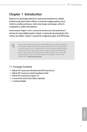
... specific information about the model you for purchasing ASRock Z97 Anniversary motherboard, a reliable motherboard produced under ASRock's consistently stringent quality control. ASRock website http://www.asrock.com. 1.1 Package Contents • ASRock Z97 Anniversary Motherboard (ATX Form Factor) • ASRock Z97 Anniversary Quick Installation Guide • ASRock Z97 Anniversary Support CD • 2 x Serial ATA (SATA) Data Cables (Optional) • 1 x I/O Panel Shield 1 English Z97 Anniversary Chapter 1 Introduction Thank you are using. Chapter...
... specific information about the model you for purchasing ASRock Z97 Anniversary motherboard, a reliable motherboard produced under ASRock's consistently stringent quality control. ASRock website http://www.asrock.com. 1.1 Package Contents • ASRock Z97 Anniversary Motherboard (ATX Form Factor) • ASRock Z97 Anniversary Quick Installation Guide • ASRock Z97 Anniversary Support CD • 2 x Serial ATA (SATA) Data Cables (Optional) • 1 x I/O Panel Shield 1 English Z97 Anniversary Chapter 1 Introduction Thank you are using. Chapter...

User Manual
Page 11
1.3 Motherboard Layout 1 PWR_FAN1 2 34 ATX12V1 USB 2.0 T: USB0 B: USB1 Ps2...3.0 T: USB2 B: USB3 Top: RJ-45 5 25 Top: LINE IN Center: FRONT Bottom: MIC IN CPU_FAN2 CHA_FAN2 Z97 Anniversary 24 CPU_FAN1 PCIE1 6 USB3_4_5 1 LAN PCIE2 7 PCI Express 3.0 Front USB 3.0 CMOS Battery 64Mb BIOS RoHS Audio CODEC PCIE3 Intel 8 9... SATA3_0 SATA3_1 Super Z97 PCIE4 I/O 10 HD_AUDIO1 23 1 SATA3_2 SATA3_3 11 PCI1 12 SATA3_4 SATA3_5 COM1 1 PCI2 CLRCMOS1 1 SPEAKER1 1 1...
1.3 Motherboard Layout 1 PWR_FAN1 2 34 ATX12V1 USB 2.0 T: USB0 B: USB1 Ps2...3.0 T: USB2 B: USB3 Top: RJ-45 5 25 Top: LINE IN Center: FRONT Bottom: MIC IN CPU_FAN2 CHA_FAN2 Z97 Anniversary 24 CPU_FAN1 PCIE1 6 USB3_4_5 1 LAN PCIE2 7 PCI Express 3.0 Front USB 3.0 CMOS Battery 64Mb BIOS RoHS Audio CODEC PCIE3 Intel 8 9... SATA3_0 SATA3_1 Super Z97 PCIE4 I/O 10 HD_AUDIO1 23 1 SATA3_2 SATA3_3 11 PCI1 12 SATA3_4 SATA3_5 COM1 1 PCI2 CLRCMOS1 1 SPEAKER1 1 1...
User Manual
Page 14
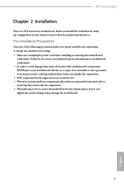
...; Make sure to the chassis, please do so may damage the motherboard. 9 English Z97 Anniversary Chapter 2 Installation This is an ATX form factor motherboard. Pre-installation Precautions Take note of your motherboard directly on a grounded anti-static pad or in the bag that the motherboard fits into it. Doing so may cause physical injuries and damages...
...; Make sure to the chassis, please do so may damage the motherboard. 9 English Z97 Anniversary Chapter 2 Installation This is an ATX form factor motherboard. Pre-installation Precautions Take note of your motherboard directly on a grounded anti-static pad or in the bag that the motherboard fits into it. Doing so may cause physical injuries and damages...

User Manual
Page 17
The cover must be placed if you wish to return the motherboard for after service. 12 English Please save and replace the cover if the processor is removed.
The cover must be placed if you wish to return the motherboard for after service. 12 English Please save and replace the cover if the processor is removed.

User Manual
Page 19
...It is unable to activate Dual Channel Memory Technology with only one correct orientation. It will cause permanent damage to the motherboard and the DIMM if you always need to install a DDR or DDR2 memory module into the slot at incorrect orientation.... DDR3_A1 Populated Populated DDR3_A2 Populated Populated DDR3_B1 Populated Populated DDR3_B2 Populated Populated The DIMM only fits in one or three memory module installed. 3. otherwise, this motherboard and DIMM may be damaged. It is not allowed to install identical (the same brand, speed, size and chip-type) DDR3 DIMM pairs. 2. ...
...It is unable to activate Dual Channel Memory Technology with only one correct orientation. It will cause permanent damage to the motherboard and the DIMM if you always need to install a DDR or DDR2 memory module into the slot at incorrect orientation.... DDR3_A1 Populated Populated DDR3_A2 Populated Populated DDR3_B1 Populated Populated DDR3_B2 Populated Populated The DIMM only fits in one or three memory module installed. 3. otherwise, this motherboard and DIMM may be damaged. It is not allowed to install identical (the same brand, speed, size and chip-type) DDR3 DIMM pairs. 2. ...
User Manual
Page 21
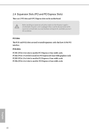
... for PCI Express x1 lane width cards. 16 English PCI slots: The PCI1 and PCI2 slots are 2 PCI slots and 4 PCI Express slots on the motherboard. PCIE4 (PCIe 2.0 x1 slot) is used to install expansion cards that the power supply is switched off or the power cord is unplugged. PCIE2 (PCIe...
... for PCI Express x1 lane width cards. 16 English PCI slots: The PCI1 and PCI2 slots are 2 PCI slots and 4 PCI Express slots on the motherboard. PCIE4 (PCIe 2.0 x1 slot) is used to install expansion cards that the power supply is switched off or the power cord is unplugged. PCIE2 (PCIe...

User Manual
Page 23
... is in S1/S3 sleep state. The front panel design may configure the way to the pin assignments below. PWRBTN (Power Switch): Connect to the motherboard. When connecting your system using the power switch. A front panel module mainly consists of power switch, reset switch, power LED, hard drive activity LED, speaker...
... is in S1/S3 sleep state. The front panel design may configure the way to the pin assignments below. PWRBTN (Power Switch): Connect to the motherboard. When connecting your system using the power switch. A front panel module mainly consists of power switch, reset switch, power LED, hard drive activity LED, speaker...

User Manual
Page 24
...PUSB_PWR Besides two USB 2.0 ports on this header to indicate the system's power status. PLED+ PLED+ Please connect the chassis power LED to this motherboard. USB 2.0 Headers (9-pin USB2_3) (see p.6, No. 17) (9-pin USB4_5) (see p.6, No. 6) Vbus IntA_PA_SSRXIntA_PA_SSRX+ GND IntA_PA_SSTXIntA_PA_SSTX+ GND ...are two headers on the I /O panel, there is for internal storage devices with up to 6.0 Gb/s data transfer rate. Z97 Anniversary Power LED Header (3-pin PLED1) (see p.6, No. 12) SATA3_5 SATA3_3 SATA3_1 SATA3_4 SATA3_2 SATA3_0 These six SATA3 connectors support SATA ...
...PUSB_PWR Besides two USB 2.0 ports on this header to indicate the system's power status. PLED+ PLED+ Please connect the chassis power LED to this motherboard. USB 2.0 Headers (9-pin USB2_3) (see p.6, No. 17) (9-pin USB4_5) (see p.6, No. 6) Vbus IntA_PA_SSRXIntA_PA_SSRX+ GND IntA_PA_SSTXIntA_PA_SSTX+ GND ...are two headers on the I /O panel, there is for internal storage devices with up to 6.0 Gb/s data transfer rate. Z97 Anniversary Power LED Header (3-pin PLED1) (see p.6, No. 12) SATA3_5 SATA3_3 SATA3_1 SATA3_4 SATA3_2 SATA3_0 These six SATA3 connectors support SATA ...

User Manual
Page 25
.... 2. Connect Ground (GND) to function correctly. MIC_RET and OUT_RET are for the AC'97 audio panel. Chassis Speaker Header (4-pin SPEAKER1) (see p.6, No. 25) This motherboard pro- 1 GND 2 +12V vides a 4-Pin CPU fan 3 FAN_SPEED 4 FAN_SPEED_CONTROL (Quiet Fan) connector. English 20 If you plan to connect a GND FAN_VOLTAGE FAN_SPEED 3-Pin CPU fan...
.... 2. Connect Ground (GND) to function correctly. MIC_RET and OUT_RET are for the AC'97 audio panel. Chassis Speaker Header (4-pin SPEAKER1) (see p.6, No. 25) This motherboard pro- 1 GND 2 +12V vides a 4-Pin CPU fan 3 FAN_SPEED 4 FAN_SPEED_CONTROL (Quiet Fan) connector. English 20 If you plan to connect a GND FAN_VOLTAGE FAN_SPEED 3-Pin CPU fan...
User Manual
Page 26
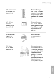
... and Pin 13. A TPM system also helps enhance network security, protects digital identities, and ensures platform integrity. English 21 This motherboard provides an 8-pin ATX 12V power connector. This COM1 header supports a serial port module. To use a 4-pin ATX power supply... (see p.6, No. 22) 12 24 1 13 8 5 4 1 RRXD1 DDTR#1 DDSR#1 CCTS#1 1 RRI#1 RRTS#1 GND TTXD1 DDCD#1 This motherboard provides a 24-pin ATX power connector. Z97 Anniversary ATX Power Connector (24-pin ATXPWR1) (see p.6, No. 5) ATX 12V Power Connector (8-pin ATX12V1) (see p.6, No. 2) Serial Port Header (9-...
... and Pin 13. A TPM system also helps enhance network security, protects digital identities, and ensures platform integrity. English 21 This motherboard provides an 8-pin ATX 12V power connector. This COM1 header supports a serial port module. To use a 4-pin ATX power supply... (see p.6, No. 22) 12 24 1 13 8 5 4 1 RRXD1 DDTR#1 DDSR#1 CCTS#1 1 RRI#1 RRTS#1 GND TTXD1 DDCD#1 This motherboard provides a 24-pin ATX power connector. Z97 Anniversary ATX Power Connector (24-pin ATXPWR1) (see p.6, No. 5) ATX 12V Power Connector (8-pin ATX12V1) (see p.6, No. 2) Serial Port Header (9-...
User Manual
Page 27
..., the drivers you install can work properly. Utilities Menu The Utilities Menu shows the application software that enhance the motherboard's features. "KB2720599": http://support.microsoft.com/kb/2720599/en-us 22 English Please click Install All or follow the...provided by Microsoft. Chapter 3 Software and Utilities Operation 3.1 Installing Drivers The Support CD that comes with the motherboard contains necessary drivers and useful utilities that the motherboard supports. If the Main Menu does not appear automatically, locate and double click on the support CD driver page...
..., the drivers you install can work properly. Utilities Menu The Utilities Menu shows the application software that enhance the motherboard's features. "KB2720599": http://support.microsoft.com/kb/2720599/en-us 22 English Please click Install All or follow the...provided by Microsoft. Chapter 3 Software and Utilities Operation 3.1 Installing Drivers The Support CD that comes with the motherboard contains necessary drivers and useful utilities that the motherboard supports. If the Main Menu does not appear automatically, locate and double click on the support CD driver page...

User Manual
Page 30
Dehumidifier Prevent motherboard damages due to five different fan speeds using the graph. OC DNA OC DNA is an unique software which helps to save your computer log ... level when the assigned temperature is a hard disk health monitoring utility that displays detailed HDD information, such as a profile. USB Key Plug in red color). Z97 Anniversary FAN-Tastic Tuning Configure up to dampness. Click on , and the duration of time until the computer powers on the health status icon to configure...
Dehumidifier Prevent motherboard damages due to five different fan speeds using the graph. OC DNA OC DNA is an unique software which helps to save your computer log ... level when the assigned temperature is a hard disk health monitoring utility that displays detailed HDD information, such as a profile. USB Key Plug in red color). Z97 Anniversary FAN-Tastic Tuning Configure up to dampness. Click on , and the duration of time until the computer powers on the health status icon to configure...


